
Loading device of leg extension machine

Inactive Publication Date: 2010-03-16
CHIA HUA FITNESS
View PDF4 Cites 13 Cited by
  • Summary
  • Abstract
  • Description
  • Claims
  • Application Information

AI Technical Summary

Benefits of technology

[0011]It is a primary object of the invention to provide a loading device of a leg extension machine, wherein the torque of a main shaft of a motor is used to replace traditional weight stacks to achieve a light and simple structure, such that the weight, volume, and noise of the machine can be reduced effectively.
[0012]Another object of the invention is to provide a loading device of a leg extension machine, wherein the linear relation and the direct proportion between the torque and the current of a DC motor or a brushless motor is used. The larger the current, the larger is the torque of the motor. If the current is reduced, then the torque of the motor will be decreased. The aforementioned principle is used to control the exercise load, so that the leg extension machine can achieve the computerized adjustment and comfortable using effects.
[0014]Still another object of the invention is to provide a loading device of a leg extension machine for monitoring an exerciser's heartbeat rate. If the exerciser's heartbeat rate exceeds a safe range, then the load will be reduced automatically to drop the heartbeat rate gradually to the safe range and assure the exerciser's health.

Problems solved by technology

On the other hand, the conventional extension machine does not have these functions.

Method used


Image

  • Loading device of leg extension machine
  • Loading device of leg extension machine
  • Loading device of leg extension machine

Examples


Embodiment Construction

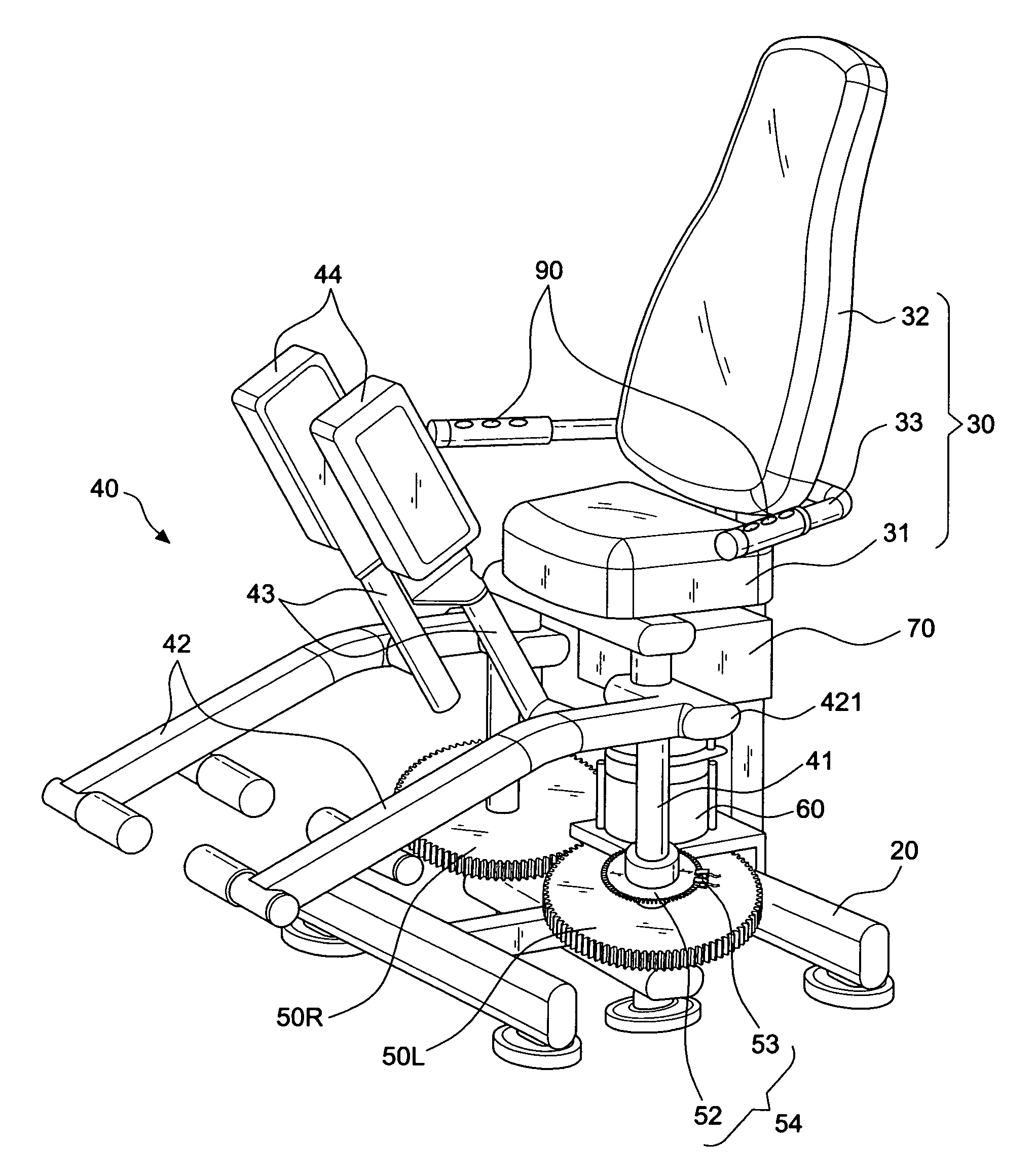
[0035]With reference to FIGS. 3 to 5 for a first preferred embodiment of the present invention, the embodiment comprises:

[0036]a base frame 20, made of a plurality of support frames;

[0037]a base body 30, disposed on the base frame 20, and having a seat cushion 31, a backrest cushion 32, and left and right handrails 33;

[0038]left and right leg extension elements 40, disposed symmetrically at opposite positions between the base frame 20 and the base body 30, and each leg extension element 40 including: an axle 41 pivotally coupled between the base frame 20 and the bottom of the base body 30, and an inner lateral end 421 and the axle 41 fixing and linking a first rod 42 to extend the first rod 42 forward to the length of the exerciser's leg by the axle 41, and a second rod 43, installed at an inner side of the middle section of the first rod 42 and extended from bottom to top, and having a pad 44 installed thereon. However, the aforementioned assembly is a prior art, and thus will not ...


PUM


Abstract

A loading device of a leg extension machine includes: a set of symmetric left and right gear disks linked and engaged with each other and installed onto two axles of left and right leg extension elements respectively, such that if the leg extension elements are pulled apart or pressed together, the two axles drive the left and right gear disks to rotate in opposite directions synchronously; a motor having a first gear installed on a main shaft and engaged with one of the left and right gear disks and a second gear engaged between the first gear and the gear disks for producing a driving resistance to the left and right gear disks synchronously; a current controller, provided for an exerciser to adjust the current transmitted to the motor through a microcomputer control panel; and a movement path sensor, for using pulse signals generated by a pair of optical couplers as feedback positions and determining the positive or negative rotation if the axle drives the optical interrupt disk, so as to control a curved load, and appropriately compensate the load current to provide a smooth and real-world setting.

Description

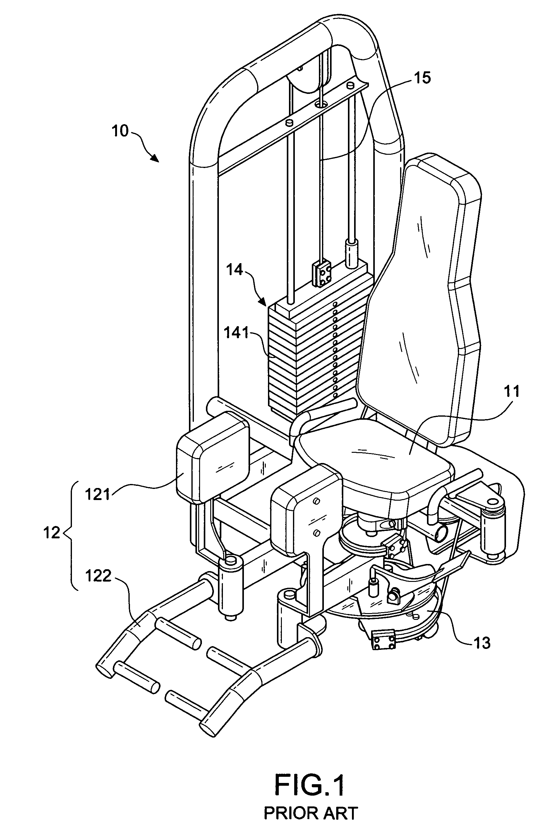
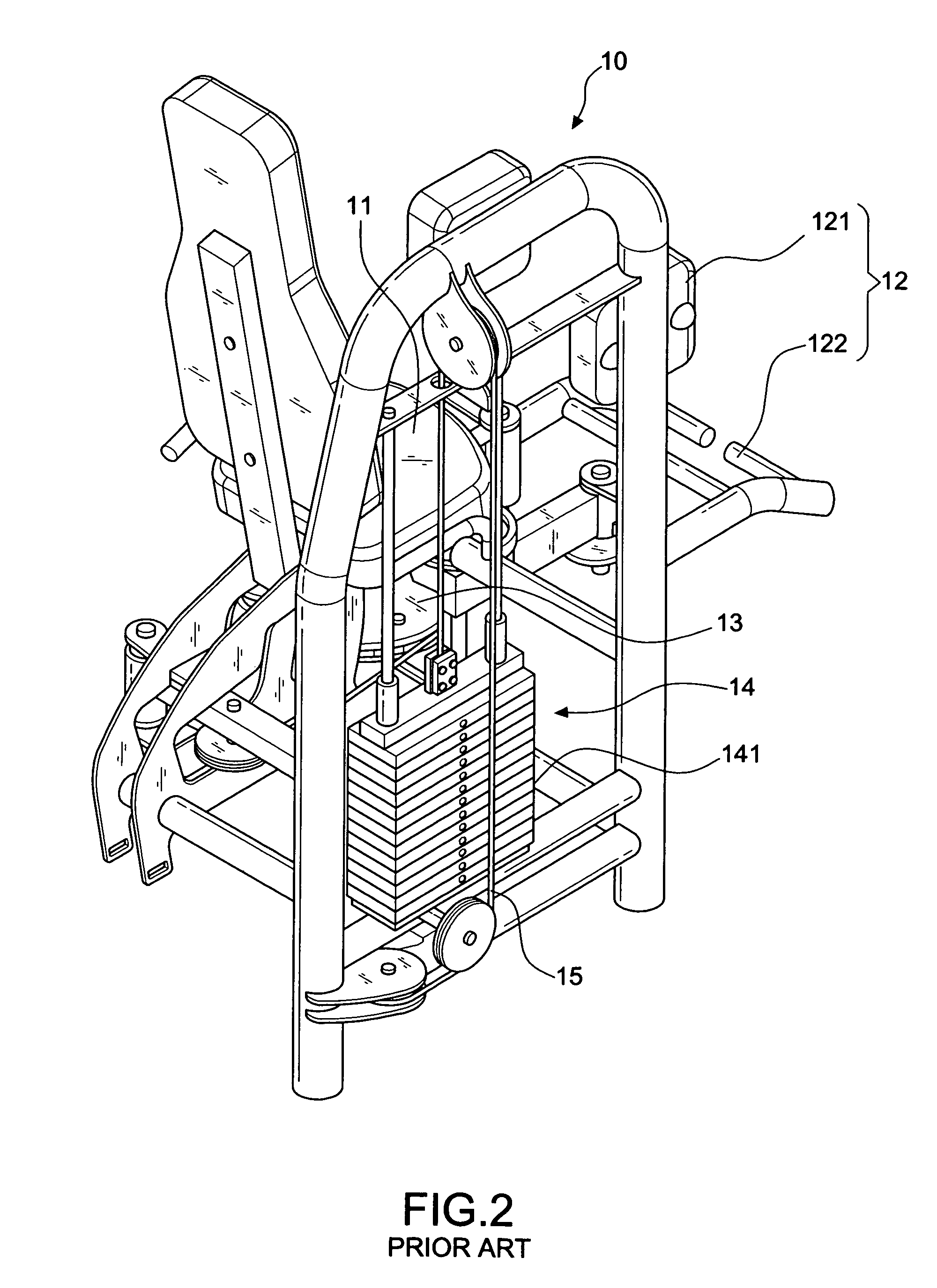
BACKGROUND OF THE INVENTION[0001]1. Field of the Invention[0002]The present invention relates to a loading device of a leg extension machine, in particular to a loading device using the linear proportion between current and torque of a DC or brushless motor and a pair of gear disks as resistance components to improve traditional exercise loads.[0003]2. Description of the Related Art[0004]Various different types of fitness equipments are designed according to different fitness exercises. For instance, a treadmill machine is designed specially for jogging or running, and a leg extension machine is designed specially for training abductor and adductor (inner and outer thigh muscles) and leg and foot muscles, and these machines were disclosed in U.S. Pat. Nos. 7,396,319, 5,575,744 and 4,478,411.[0005]In addition to leg extension components, the main structure of a conventional leg extension fitness machine further includes a resistance device as disclosed in U.S. Pat. No. 7,396,319 and ...

Claims


Application Information

Patent Timeline
IPC IPC(8): A63B21/005
CPCA63B21/0051A63B21/0613A63B23/04A63B2024/0078A63B2220/51A63B2220/805A63B21/0624
Inventor HSIEH, LI-MIN
Owner CHIA HUA FITNESS
Learn More