
Moving robot

a robot and moving technology, applied in the direction of steering parts, non-deflectable wheels, vehicle components, etc., can solve the problems of not paying consideration to a countermeasure to prevent the robot from falling down, falling down, etc., to maintain the availability of traveling and the inherent merit or advantage

Inactive Publication Date: 2010-03-16
HITACHI LTD
View PDF10 Cites 41 Cited by
  • Summary
  • Abstract
  • Description
  • Claims
  • Application Information

AI Technical Summary

Benefits of technology

The robot achieves stable travel on uneven surfaces and steps while maintaining a narrow footprint, preventing falls and enabling effective operation in environments with humans, by dynamically adjusting its posture and wheel positioning to ensure balance and stability.

Problems solved by technology

Although the conventional arts disclosed in the above-mentioned Patent Documents 1 and 2 can provide stability for the robot to run on a flat or level surface, however no consideration was paid on a countermeasure for preventing the robot from an event of falling down due to un-expectable reasons.
The problem of the former, inherently accompanying the travel based on the inverted pendulum control, is caused due to an abnormal operation of the travel controlling system, or cutoff of an electric power source, so that the robot looses the balancing operation force of the moving mechanism, and thereby resulting into falling down, easily.
However, for traveling on an edge of a road or steps, which can be expected in the practical application thereof, since the driving wheels must be very large, in the diameter thereof, then the footprint of the robot itself is expanded or enlarged, undesirably, and thereby loosing an inherent merit or advantage obtainable by applying the inverted pendulum control.

Method used


Image

  • Moving robot
  • Moving robot
  • Moving robot

Examples


embodiments

[0039]Hereinafter, explanation will be given about embodiments according to the present invention, by referring to FIGS. 1(a) to 9(e) of the drawings attached herewith.

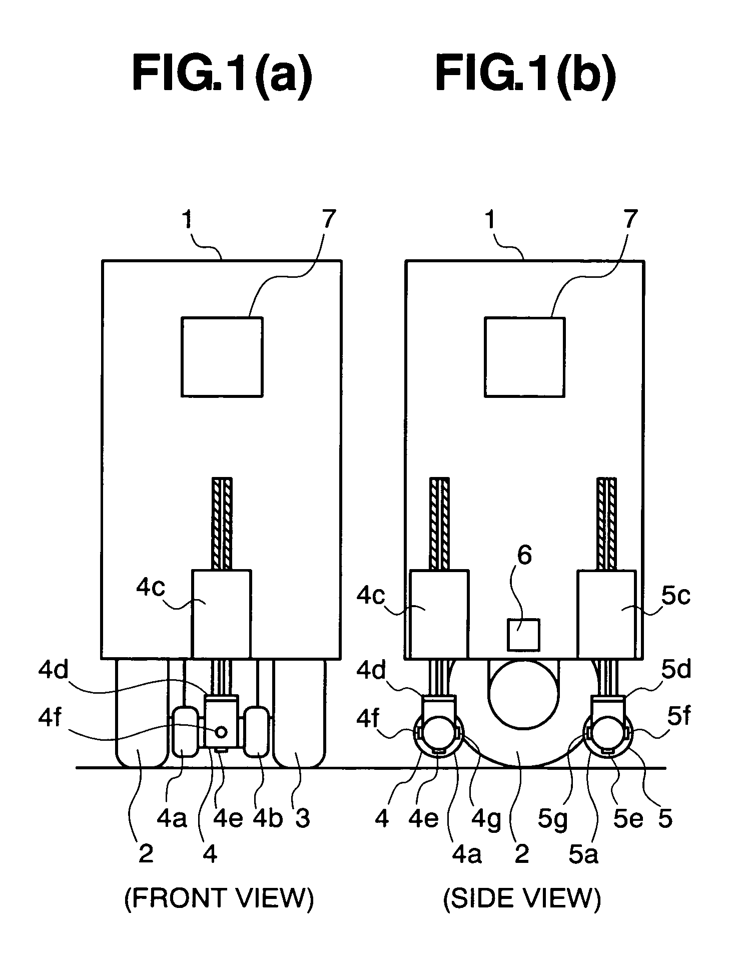
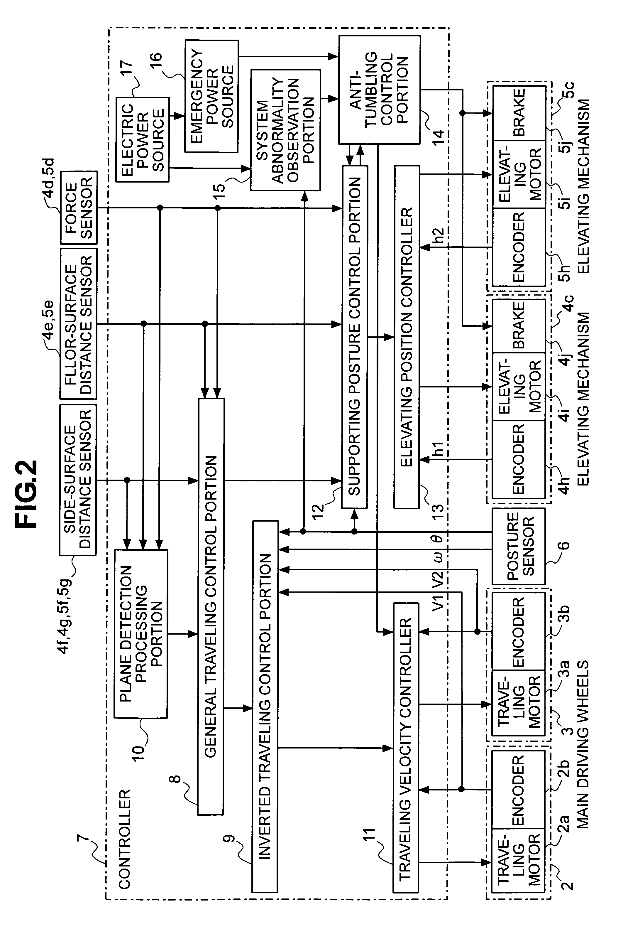
[0040]FIGS. 1(a) and 1(b) are a front view and a side view of the moving robot, according to the present embodiment, for explaining the mechanical structures thereof. FIG. 2 is the block diagram of the controlling system of the moving robot, according to the present embodiment. In those FIGS. 1(a) to 2, the similar constituent elements are given with the same reference numbers.

[0041]The moving robot 1 comprises main driving wheels 2 and 3, each of which is controlled in accordance with the inverted pendulum control, supporting legs 4 and 5, which are disposed in front and rear of those main driving wheels 2 and 3, a posture sensor 6 for detecting posture of the moving robot with respect to the direction of gravity, and a controller apparatus 7 for controlling the mechanisms of the moving robot 1, upon basis of informa...


PUM


Abstract

Within a moving robot of narrow footprint, having quick traveling performance on a plane-surface, as well as, anti-tumbling function, and further being suitable for operations under coexistence with a human being, being able to travel coping with traveling situations on a level difference, etc.: in front and rear of main driving wheels 2 and 3, each being controlled through the inverted pendulum control, are disposed supporting legs 4 and 5, tips of which can be lifted up and down, wherein the tips of the supporting legs 4 and 5 are positioned to keep a predetermined distance between a traveling surface, when running on the inverted two-wheels travel, and the supporting legs 4 and 5 are fixed or either one in the fall-down direction is thrust out into the fall-down direction, so as to protect it from falling down. Further, upon the basis of detection information of floor-surface distance sensors 4e and 5e and side-surface distance sensor 4f, 4g, 5f and 5g, which are provided at the tips of the supporting legs 4 and 5, the robot senses an existence of a level difference and / or an inclined surface, so as to let the supporting legs to escape from the level difference and / or the inclined surface, and holds the position of gravity center thereof, stably, through other one of the supporting legs, being landed on the ground, and the main driving wheels 2 and 3; thereby enabling to travel over the level difference and the inclines surface.

Description

BACKGROUND OF THE INVENTION[0001]The present invention relates to a moving robot, being able to operate under an environment of coexistence with a human being.[0002]In case when considering the forms of workings or operations with an aid of a robot, under the environment or circumstances coexisting with a human being, into the consideration, it is rational that a height of the robot be nearly equal to the size of the human being, for conducting hand works and interaction to the human being effectively. Further, in case when the robot conducts works within a limited space where it coexists with the human being, accompanying effective movements thereof, it is preferable to minimize a footprint of the robot at the smallest as possible. When achieving such requirements of the forms, a gravity center of the robot necessarily comes to be high, with respect to the footprint, and thereby lowering a stability of standing posture thereof. On the other hand, in case of letting it to conduct th...

Claims


Application Information

Patent Timeline
Patent Type & Authority Patents(United States)
IPC IPC(8): B62D61/00
CPCB62D57/024B62D57/028
Inventor HOSODA, YUJI
Owner HITACHI LTD
Learn More