
Programmable transmitter architecture for non-constant and constant envelope modulation

a transmitter and non-constant envelope technology, applied in the field of programmable transmitters, can solve the problems of circuits suffering from several drawbacks, signal distortion, and inability to meet the requirements of continuous envelope modulation bandwidth efficiency, and achieve the effect of great versatility and easy fabrication

Active Publication Date: 2010-03-02
GULA CONSULTING LLC
View PDF245 Cites 35 Cited by
  • Summary
  • Abstract
  • Description
  • Claims
  • Application Information

AI Technical Summary

Benefits of technology

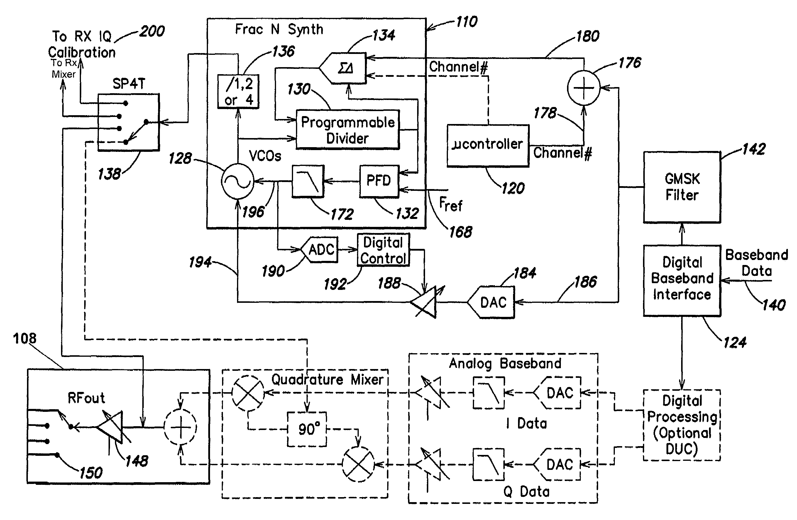
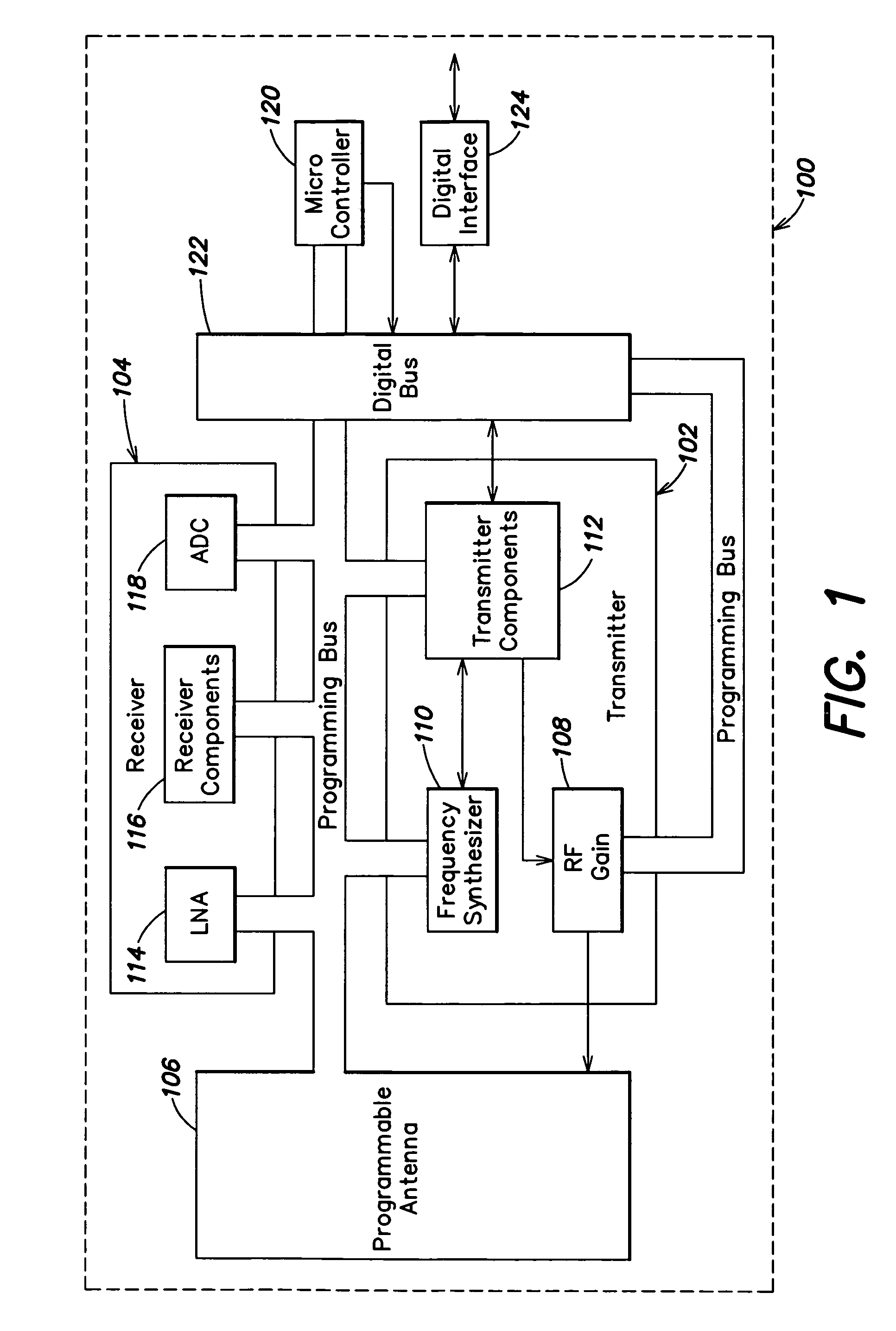
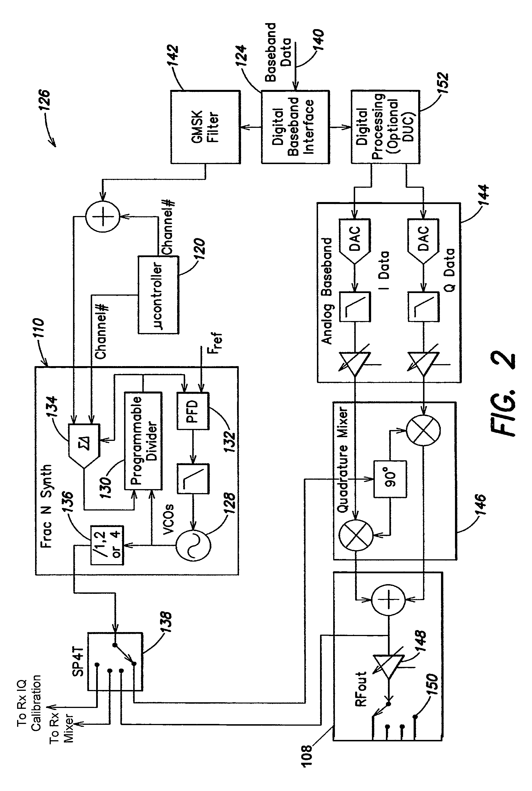
The present invention provides a flexible frequency synthesizer design that can accommodate both constant and non-constant envelope modulation schemes. The design includes multiple voltage controlled oscillators, a programmable frequency synthesizer, a programmable baseband interface, a digital-to-analog converter, a quadrature mixer, a pulse-shaping filter, a voltage controlled oscillator monitoring loop, and a digital controller. The design allows for easy customization and versatility, and can be used in various communication standards. The technical effects of the invention include improved programmability, flexibility, and power efficiency of the transmitter.

Problems solved by technology

Although constant envelope modulation is not as bandwidth efficient as is non-constant envelope modulation, it is in world-wide use as part of the GSM wireless communication standard which uses GMSK modulation.
However, these circuits can suffer from several drawbacks.
For example, in the well-known simple direct modulation transmitter, translation of the analog signal to a radio frequency signal is done in one or multiple stages, and special care must be exercised in order to ensure isolation between the power amplifier and the VCO (i.e., by minimizing coupling between the stages), otherwise cross-talk and VCO “pulling” may cause signal distortion.

Method used


Image

  • Programmable transmitter architecture for non-constant and constant envelope modulation
  • Programmable transmitter architecture for non-constant and constant envelope modulation
  • Programmable transmitter architecture for non-constant and constant envelope modulation

Examples


Embodiment Construction

[0022]Aspects and embodiments of the invention are directed to a programmable transceiver architecture that allows both constant and non-constant envelope modulation. The circuit implementation of constant and non-constant envelop modulation circuits traditionally requires two separate, distinctly different implementation approaches, including separate frequency synthesizers or phase locked loops (PLLs) for each modulation schemes. As a result, many prior art transceivers are capable of supporting only one type of envelope modulation (i.e., either constant or non-constant, but not both), or require multiple chipsets (e.g., multiple frequency synthesizers or phase-locked loop circuits) to accommodate different modulation schemes. For example, U.S. Pat. No. 6,747,987 (which is herein incorporated by reference) describes a multi-protocol, multi-band transmitter architecture that supports both constant and non-constant envelope modulation, but requires a second PLL to generate an offset...


PUM


Abstract

Transmitter architectures designed to accommodate both constant and non-constant of envelope modulation schemes and capable of providing local oscillator carrier frequencies within any one of numerous desired frequency bands, thus allowing compliance with many different communication standards. One example of a programmable frequency synthesizer includes a plurality of transmitter components and a microcontroller coupled to the frequency synthesizer and to the plurality of transmitter components. The microcontroller is adapted to provide a frequency control signal to the frequency synthesizer to control a frequency of the local oscillator carrier frequency. In addition, the microcontroller is also adapted to provide digital control signals to at least some of the plurality of transmitter components to turn on and off different ones of the plurality of transmitter components based on an operating mode of the transmitter, such that the transmitter can accommodate both constant envelope modulation and non-constant envelope modulation schemes.

Description

BACKGROUND[0001]1. Field of Invention[0002]The present invention is directed to a programmable transmitter, in particular, a transmitter architecture designed to accommodate multiple types of envelope modulation.[0003]2. Discussion of Related Art[0004]Modern modulation techniques that are part of the transceiver architecture of a wireless communication system can generally be classified as belonging to either non-constant (variable) or constant envelope modulation schemes. One example of a widely used non-constant envelope modulation scheme is the EDGE (Enhanced Data Rate for GSM Evolution) standard that was introduced with the intent to improve the data speed of GSM (Groupe Special Mobile) networks from 270.833 kilobits per second (kbps) to 812.5 kbps. EDGE utilizes a 3π / 8 eight-Phase Shift Key (PSK) modulation. Some other examples of non-constant envelope modulation schemes include Code Division Multiple Access 2000 (CDMA2k), Universal Mobil Telecommunications Systems (UMTS), inte...

Claims


Application Information

Patent Timeline
Patent Type & Authority Patents(United States)
IPC IPC(8): H04B1/40
CPCH04B1/0483H04L27/0008H04B1/406H03D7/00H04B1/04
Inventor KILPATRICK, JOHNDAWSON, JOELBOHORQUEZ, JOSEVENUTI, JEFF
Owner GULA CONSULTING LLC
Learn More