
Method of forming polycarbonate

a technology of polycarbonate and polycarbonate, which is applied in the field of polycarbonate production, can solve the problems of adversely altering the molar ratio of the reaction components (diaryl carbonate/dihydroxy), and achieve the effects of facilitating the transfer, and preventing the formation of a reaction reaction

Inactive Publication Date: 2010-03-02
SHPP GLOBAL TECH BV
View PDF64 Cites 26 Cited by
  • Summary
  • Abstract
  • Description
  • Claims
  • Application Information

AI Technical Summary

Benefits of technology

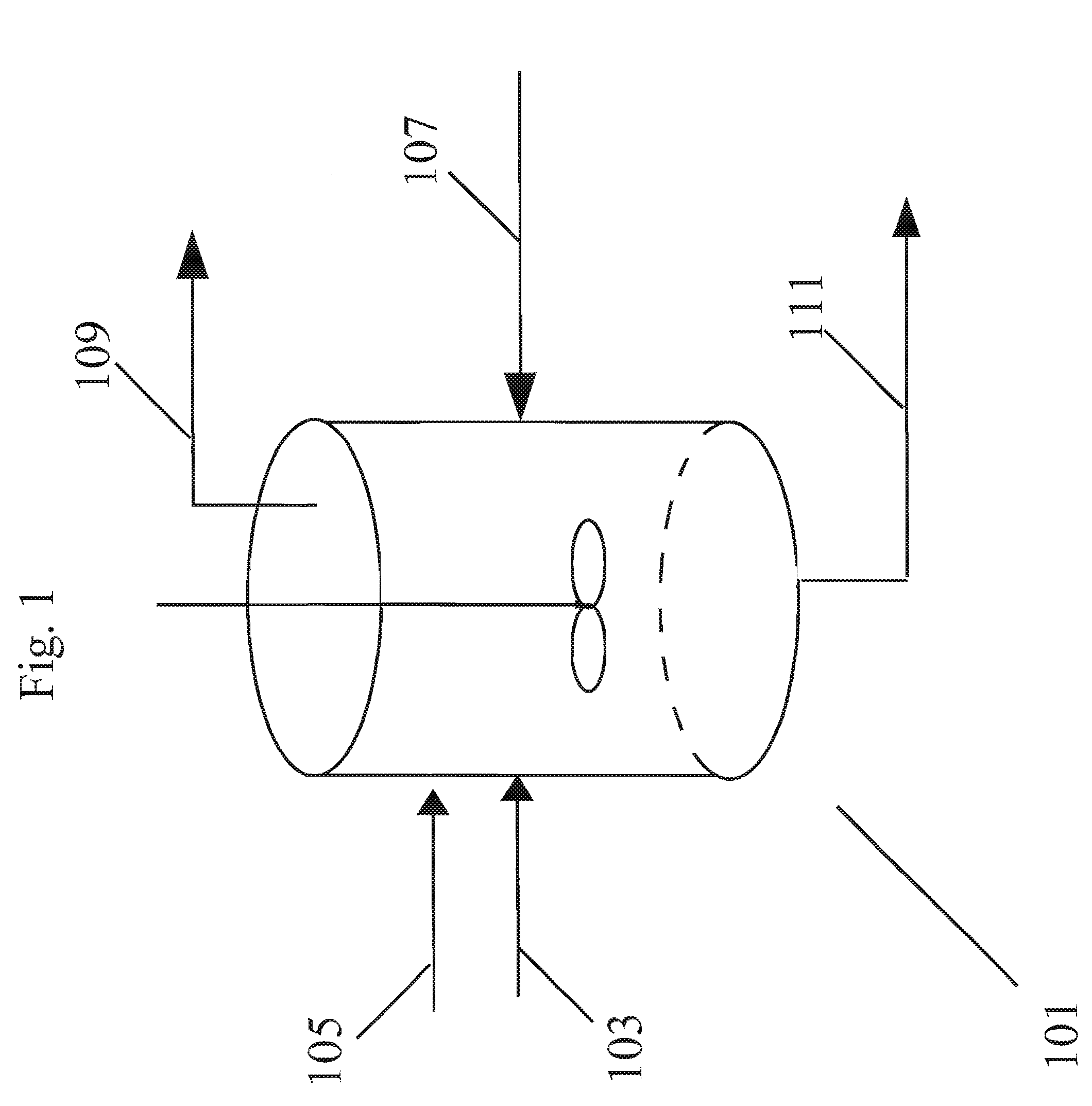
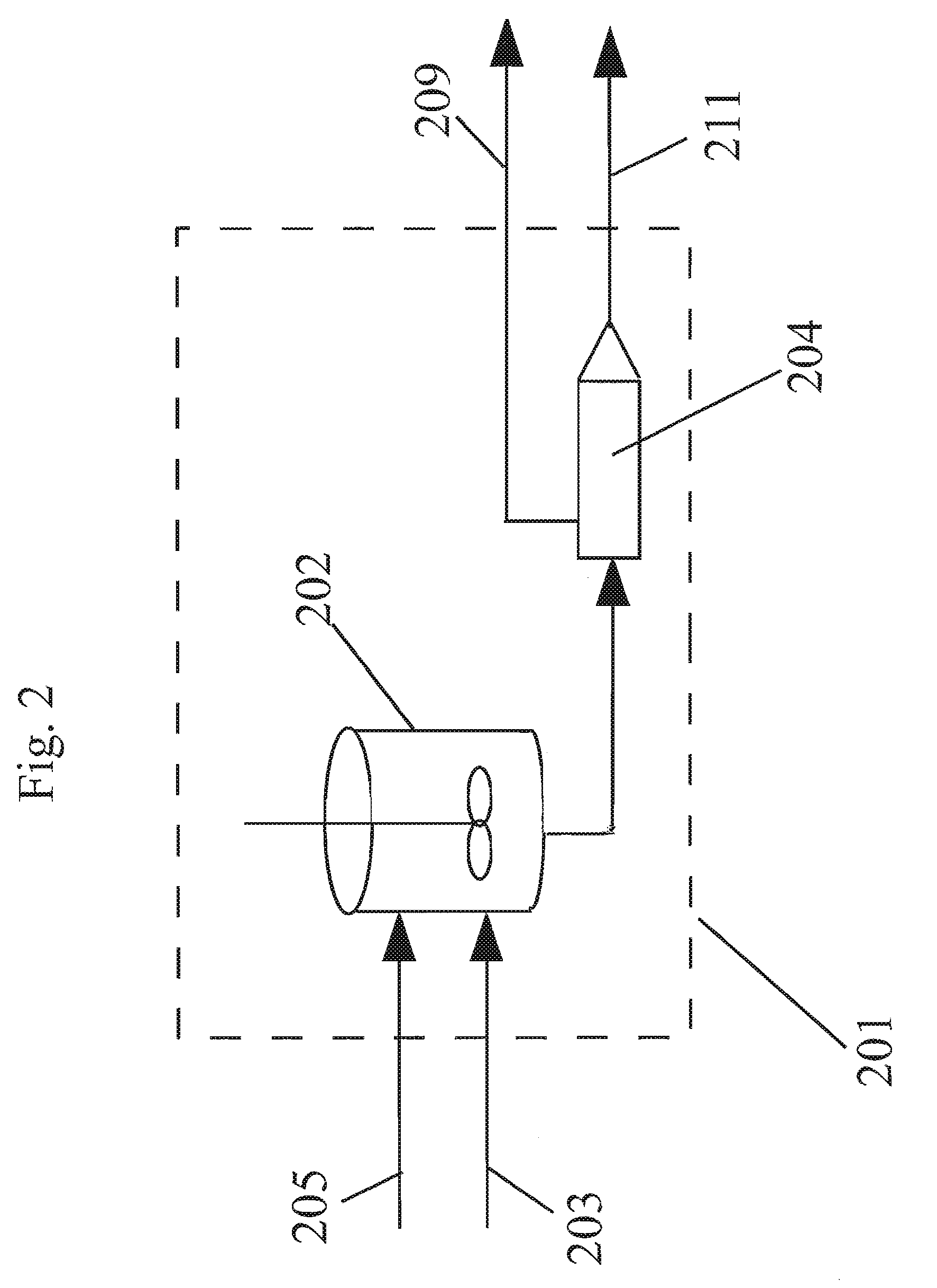
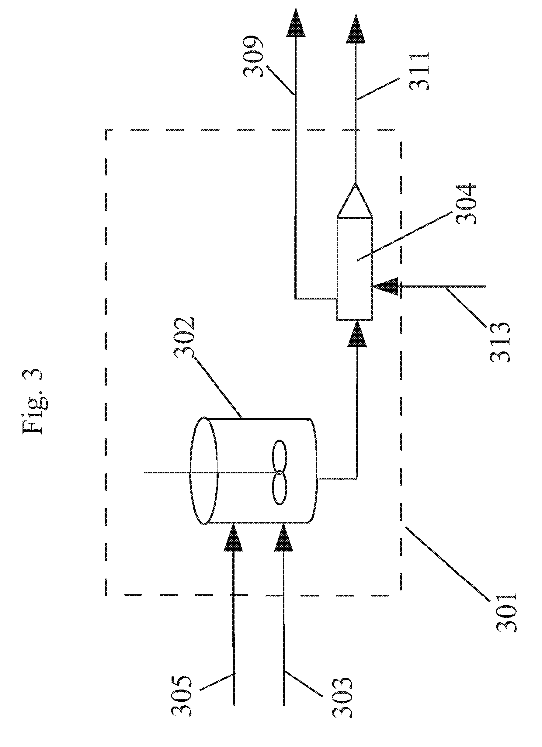
[0005]The present inventors have found that melt transesterification catalyst can be dissolved or suspended within ester-substituted phenol to produce a free flowing mixture that can be introduced to other reaction components and dispersed within a melt polymerization reaction mixture in a polymerization reactor(s). Using an ester-substituted phenol as a solvent and / or carrier liquid for these materials has been found to have many distinct and real world benefits.
[0006]First and foremost, ester-substituted phenol is a native material to melt transesterification reactions in that it is a byproduct created in the reaction between an ester-substituted diaryl carbonate and a dihydroxy compound. The ester-substituted phenol is removed from the reaction equipment, usually as a vapor, to drive the melt reaction forward to build molecular weight and produce polycarbonate. By dissolving or suspending melt polymerization catalysts in an ester-substituted phenol, one can create a free flowing mixture that can be easily transferred throughout a melt polycarbonate production facility and introduced into melt transesterification reaction equipment. Furthermore, one can easily measure and / or meter the introduction of the catalyst, within the mixture, into the reaction equipment to create desired stoichiometric conditions.

Problems solved by technology

This negatively impacts the melt polymerization reaction in that the molar ratio of reaction components (diaryl carbonate / dihydroxy) is adversely altered prior to or during the melt polymerization reaction.

Method used


Image

  • Method of forming polycarbonate
  • Method of forming polycarbonate
  • Method of forming polycarbonate

Examples


working example 1

Bismethylsalicylcarbonate (BMSC) in Methyl Salicylate (MS) Addition to the Reaction Components

[0117]A reaction mixture comprising BPA, methylhydroquinone, and hydroquinone were reacted in a melt polymerization reaction to form a terpolymer in Working Example 1. The formulated BMSC / total diol molar ratio was 1.0195. The oligomer was fed to the extruder at a rate of 13.5 kg / hr for 3 hours. Extrusion at the above conditions obtained a polymer with a PC Mw 28,479 g / mol. At this time a solution of 4% (w / w) BMSC in methyl salicylate (MS) was fed to the extruder feed line at a rate of 5 ml / min. At this flow rate a shift in BMSC / diol mol ratio of 0.002 caused a Mw drop of the polycarbonate of 1,985 g / mol down to 26,714 g / mol. As shown in FIG. 7, a corresponding systematic decrease and a step change in the torque as measured on the extruder was also observed as the BMSC was added. No operational issues were observed before and during the addition period. As shown below in Table 2, no signifi...

working example 2

BPA in MS Addition to the Reaction Components

[0119]A reaction mixture comprising BPA, methylhydroquinone, and hydroquinone were reacted in a melt polymerization reaction to form a terpolymer in Working Example 2. The formulated BMSC / diol mol ratio was 1.02. Oligomer was fed to the extruder at a rate of 13.5 kg / hr for 3 hours. Extrusion at standard conditions obtained a polymer with a PC Mw 28,244 g / mol. At this time a solution of 4% (w / w) BPA in MS was fed to the extruder feed line at a rate of 5 ml / min. At this flow rate a shift in BMSC / diol mol ratio of 0.002 caused a PC Mw increase of 3,574 g / mol up to 31,818 g / mol. As shown in FIG. 8, a corresponding systematic increase and step change in the torque as measured on the extruder was also observed as the BPA was added. No operational issues were observed before and during the addition period. As shown below in Table 3, no significant negative impact of the addition was observed on the polymer product properties such as color, resid...

working example 3

Non-Aqueous Catalyst Solution in MS / MeOH Addition to the Reaction Components

[0121]In this example a non-aqueous catalyst solution based on MS and methanol (MeOH) as co-solvent was used to polymerize on a reactive extruder an oligomer prepared by a batch oligomerization process. A reaction mixture comprising BPA, methylhydroquinone, and hydroquinone were reacted in a melt polymerization reaction to form a terpolymer in Working Example 3. The formulated BMSC / diol mol ratio was 1.0175. For 4 hours the oligomer was fed to the extruder at a rate of 11.5 kg / hr. A polymer was obtained with an average Mw 23,979 g / mol. During this time a catalyst solution of 2.5013×10⁵ mol / (mol diol) TMAA and 2.099×10⁶ mol / (mol diol) NaOH in MS / MeOH combined liquid carrier comprising an ester-substituted phenol and polar co-solvent was added to the oligomer reactor M at a flow rate of 0.2 ml / min. At the same time an additional catalyst solution of 5.981×10⁶ mol / (mol diol) NaOH in MS / MeOH was added to the ext...


PUM

PropertyMeasurementUnit
boiling pointaaaaaaaaaa

Abstract

A method of forming polycarbonate includes the steps of introducing a plurality of reaction components to a reactor operating under melt polymerization conditions and removing ester-substituted phenol from the reactor. The plurality of reaction components include a dihydroxy compound, an ester-substituted diaryl carbonate, and a melt transesterification catalyst. The reaction components are introduced in a plurality of reaction component streams. A first reaction component streams includes a melt transesterification catalyst dissolved or suspended in a liquid carrier containing an ester-substituted phenol. The composition of the first reaction component stream is selected such that ester-substituted phenol is not generated as a reaction product in the first reaction component stream.

Description

BACKGROUND OF INVENTION[0001]The present invention relates to the production of polycarbonate using a melt transesterification reaction between a diaryl carbonate and a dihydroxy compound. In the melt transesterification process, dihydroxy compounds such as bisphenol A are reacted with diaryl carbonates such as diphenyl carbonate (DPC) or more preferably with ester-substituted diaryl carbonates such as bismethylsalicylcarbonate (BMSC).[0002]U.S. Pat. No. 4,323,668, which is incorporated herein by reference, describes a polycarbonate transesterification process comprising reacting an ester-substituted diaryl carbonate and a dihydric phenol in the presence of a catalyst under transesterification reaction conditions. In the specific examples, U.S. Pat. No. 4,323,668, which is incorporated herein by reference, makes uses of bismethylsalicylcarbonate (BMSC) as the diaryl carbonate. Use of ester-substituted diaryl carbonates in the production of polycarbonate is also described in U.S. Pat...

Claims


Application Information

Patent Timeline
Patent Type & Authority Patents(United States)
IPC IPC(8): C08G64/00B28B3/20
CPCB01J19/1862B01J19/20C08G64/205C08G64/307B01J2219/0004
Inventor BRACK, HANS-PETERDAVIS, PETER K.DOMINGO FUSTER, DAVIDGARCIA AGUDO, JORGEHIDALGO LLINAS, GERARDOSALOMON CHELIZ, MIGUEL ANGELVIC FERNANDEZ, IGNACIOVAN DER WEKKE, LAURUSWILLEMSE, DENNIS JAMES PATRICK MARIA
Owner SHPP GLOBAL TECH BV
Learn More