
Exhaust muffling device

a technology of exhaust muffling and muffling chamber, which is applied in the direction of gas passages, instruments, gas chambers, etc., can solve the problems of increasing costs and achieve the effect of long wavelength and difficult muffl

Inactive Publication Date: 2010-03-02
TOYOTA JIDOSHA KK
View PDF34 Cites 17 Cited by
  • Summary
  • Abstract
  • Description
  • Claims
  • Application Information

AI Technical Summary

Benefits of technology

[0004]An object of the present invention is to provide an exhaust muffling device having a simple structure, which is capable of suppressing air column resonance favorably, irrespective of the length of an outlet pipe of an exhaust pipe connected to a muffler, and with which it is possible to achieve appropriate reductions in weight and cost.
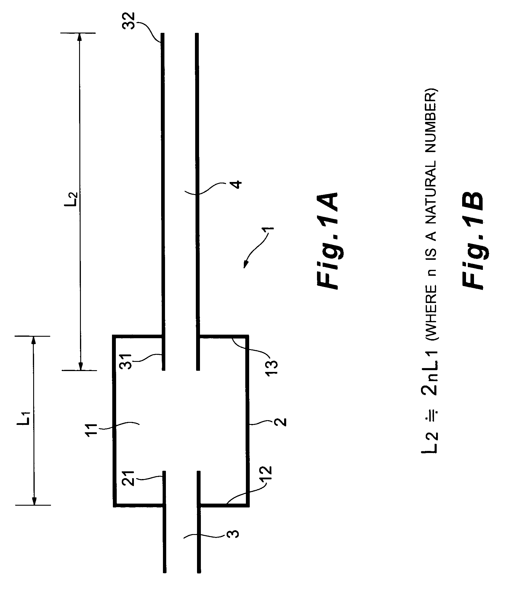
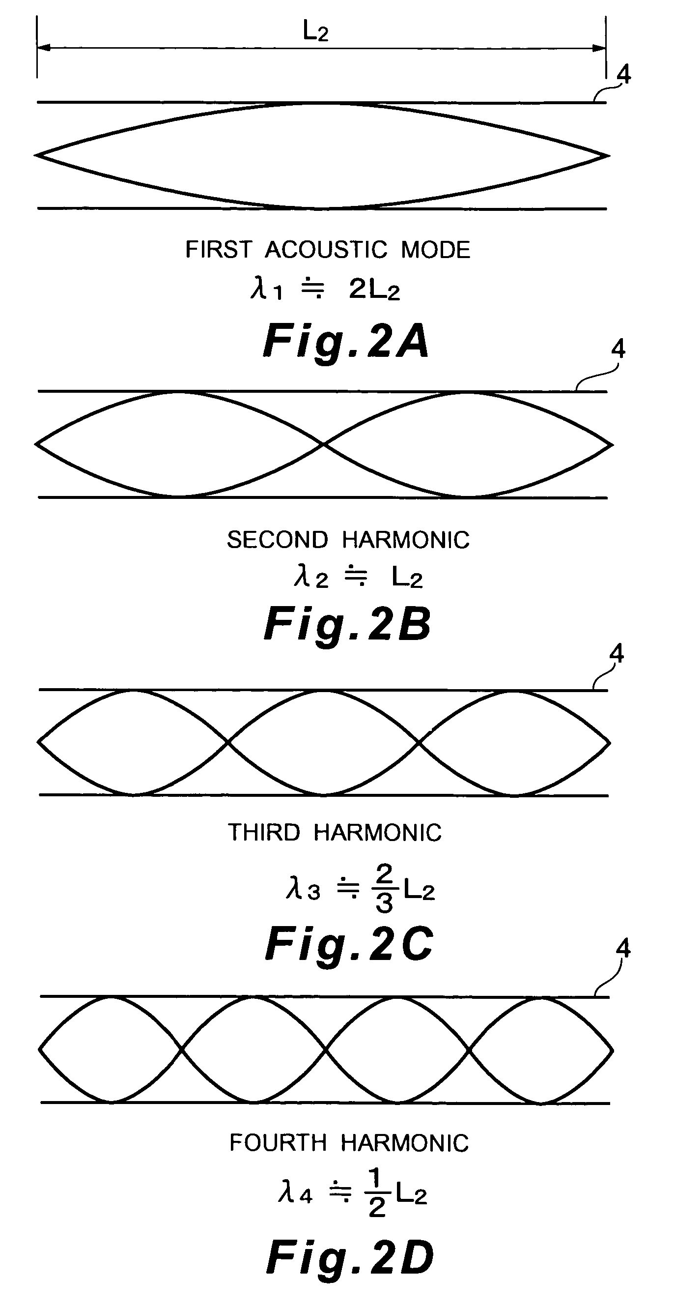
[0011]According to this constitution, when air column resonance is generated inside the outlet pipe in accordance with a partial length (to be referred to hereinafter as the “substantial air column length”) of the outlet pipe from the through hole formed in the peripheral wall thereof to the second open end face, a relationship of expansion chamber length:substantial air column length being approximately 1:2n is established, and hence air column resonance of the nth harmonic can be suppressed effectively by means of an interference effect inside the expansion chamber in a similar manner to that described above.
[0015]According to the exhaust muffling device of the present invention, air column resonance can be suppressed favorably using a simple structure, irrespective of the length of the outlet pipe, thereby enabling an improvement in the muffling performance. As a result, a separate sub-muffler does not have to be provided in the outlet pipe, enabling appropriate reductions in weight and cost.

Problems solved by technology

However, the overall weight is increased by the provision of the plurality of mufflers, which is likely to lead to an increase in cost.

Method used


Image

  • Exhaust muffling device
  • Exhaust muffling device
  • Exhaust muffling device

Examples


first embodiment

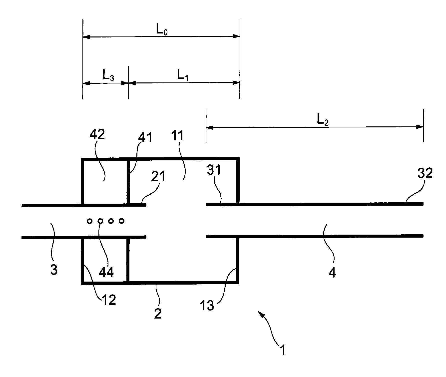
[0026]As shown in FIG. 1, an exhaust muffling device 1 comprises a muffler 2 for muffling the exhaust noise of exhaust gas discharged from an internal combustion engine, an inlet pipe 3 of an exhaust pipe for introducing the exhaust gas into the muffler 2 from the internal combustion engine, and an outlet pipe 4 of the exhaust pipe for discharging the exhaust gas outside from the muffler 2.

[0027]A single expansion chamber 11 having a length of L1 in an exhaust direction is disposed in an interior of the muffler 2. The expansion chamber 11 is formed with a larger exhaust gas passage sectional area than the inlet pipe 3, and hence the pressure of the exhaust gas that flows into the expansion chamber 11 from the inlet pipe 3 decreases. The length L1 of the expansion chamber 11 in this case corresponds to a distance between inner walls 12, 13 facing each other in the exhaust direction of the muffler 2.

[0028]One open end portion of the inlet pipe 3 communicates with an exhaust manifold, ...

second embodiment

[0036]As shown in FIG. 3, the interior of the muffler 2 in the exhaust muffling device 1 according to a second embodiment is separated into a resonance chamber 42 disposed on the inlet pipe 3 side, and the expansion chamber 11 disposed on the outlet pipe 4 side, using a separator 41. The length L1 of the expansion chamber 11 in the exhaust direction corresponds to a distance from the separator 41 to the inner wall 13 of the muffler 2 near the outlet pipe 4. The resonance chamber 42 serves to resonate with oscillation of a specific frequency in order to reduce the level of the exhaust noise caused by this oscillation. A length L3 of the resonance chamber 42 in the exhaust direction is set to a length obtained by subtracting the length L1 of the expansion chamber 11 from an entire length L0 of the muffler 2 in the exhaust direction. An open end portion 21 of the inlet pipe 3 on the muffler 2 side communicates with the expansion chamber 11 via the resonance chamber 42, and a plurality ...

third embodiment

[0038]As shown in FIG. 4, in the exhaust muffling device 1 according to a third embodiment, the inlet pipe 3 and outlet pipe 4 communicating with the expansion chamber 11 inside the muffler 2 are not disposed coaxially. Further, these pipes 3, 4 are inserted more deeply into the muffler 2 than in the first embodiment such that they overlap. An entire length of the outlet pipe 4 is set to L4, and an open end portion 31 thereof near one open end face 33 communicates with the expansion chamber 11. The outlet pipe 4 comprises a plurality of bypass holes 51 (through holes) formed in a peripheral wall thereof in positions on the inner wall 13 side near the open end portion 31. The plurality of bypass holes 51 communicate with the expansion chamber 11.

[0039]In this embodiment, air column resonance is generated inside the outlet pipe 4 in accordance with a pipe length from an open end face 34 near the other open end portion 32 of the outlet pipe 4, which communicates with the outside, to th...


PUM


Abstract

An object of the present invention is to provide an exhaust muffling device having a simple structure, which is capable of suppressing air column resonance favorably, irrespective of a length of an outlet pipe of an exhaust pipe which communicates with a muffler, and with which it is possible to achieve appropriate reductions in weight and cost. The exhaust muffling device of the present invention comprises a muffler having an expansion chamber whose length is L in an exhaust direction, and an outlet pipe being in communication with the expansion chamber and whose pipe length is approximately 2nL in which n is a natural number.

Description

BACKGROUND[0001]The present invention relates to an exhaust muffling device for reducing exhaust noise by suppressing air column resonance.[0002]Conventionally, in this type of exhaust muffling device installed in an internal combustion engine, a plurality of mufflers are arranged-over an exhaust pipe which communicates with an exhaust manifold in order to suppress air column resonance generated in the exhaust pipe. For example, a constitution is known whereby a length from a convergence point of an exhaust manifold to a terminal outlet of an exhaust pipe is set as a reference length (X), a first muffler is provided in a position of 3X / 5 from the terminal outlet, and a second muffler is provided in a position of 2X / 5 from the terminal outlet. This type of exhaust muffling device is disclosed in Japanese Laid-Open Patent Publication No. S59-226222.[0003]By providing a plurality of mufflers in appropriate locations, this type of conventional exhaust muffling device is capable of muffl...

Claims


Application Information

Patent Timeline
Patent Type & Authority Patents(United States)
IPC IPC(8): F01N1/02F01N1/06F01N1/08G10K11/16
CPCF01N1/02F01N1/084F01N1/089F01N2470/20F01N2490/18
Inventor YAMAGUCHI, JUNICHIKONDO, TADASHI
Owner TOYOTA JIDOSHA KK
Learn More