Arrangement structure for auxiliary component of vehicle
a technology for auxiliary components and arrangement structures, applied in child seats, roofs, transportation and packaging, etc., can solve problems such as reducing the size of auxiliary components of vehicles, and achieve the effect of improving layout flexibility
- Summary
- Abstract
- Description
- Claims
- Application Information
AI Technical Summary
Benefits of technology
Problems solved by technology
Method used
Image
Examples
first embodiment
[0059]With reference to the drawings, the present invention will now be described.
[0060]FIGS. 1 and 2 are side views showing an arrangement structure for an auxiliary component of a vehicle, according to the first embodiment, viewed, respectively, from the side of a driver's seat Dr and from the side of a front passenger seat Pa.
[0061]A lower dash panel (dash panel) 1 is disposed in a front region of a vehicle to partition between an engine compartment E and a passenger compartment R in a frontward / rearward or longitudinal direction of a vehicle body. A floor panel 2 is connected to a rear side of a lower edge of the lower dash panel 1 to extend approximately horizontally toward a rear region of the vehicle. The floor panel 2 defines a lower surface (bottom surface) of the passenger compartment R.
[0062]FIG. 3 is a perspective view showing the floor panel 2. The floor panel 2 has a kick-up area 3 stepped upward in a rear region thereof. The kick-up area 3 includes a first kick-up por...
second embodiment
[0107]With reference to the drawings, the present invention will be described below.
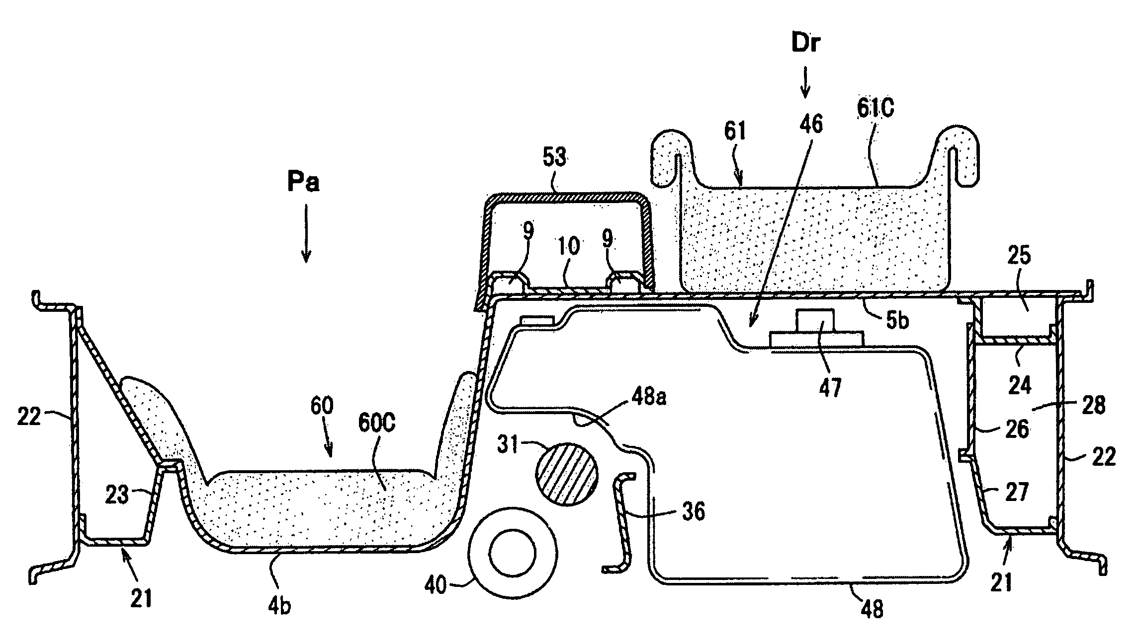
[0108]FIG. 18 is a side view showing an arrangement structure for an auxiliary component of a vehicle, according to the second embodiment, viewed from the driver's-seat side Dr, and FIG. 19 is a detail view showing the auxiliary-component arrangement structure in FIG. 18. FIG. 20 is a side view showing the auxiliary-component arrangement structure in FIG. 18, viewed from the front-passenger-seat side Pa. FIG. 21 is a perspective view showing a floor panel 2, and FIG. 22 is a top plan view showing a passenger compartment of the vehicle in FIG. 18.
[0109]As with the first embodiment, a bottom surface of a passenger compartment R is defined by the floor panel 2. The floor panel 2 has a rear region formed as a first kick-up portion 4 on the front-passenger-seat side Pa and a second kick-up portion 5 on the driver's-seat side Dr, and the second kick-up portion 5 is formed to have a height greater than that...
PUM
 Abstract
Description
Claims
Application Information
 - R&D
- Intellectual Property
- Life Sciences
- Materials
- Tech Scout
- Unparalleled Data Quality
- Higher Quality Content
- 60% Fewer Hallucinations
Browse by: Latest US Patents, China's latest patents, Technical Efficacy Thesaurus, Application Domain, Technology Topic, Popular Technical Reports.
© 2025 PatSnap. All rights reserved.Legal|Privacy policy|Modern Slavery Act Transparency Statement|Sitemap|About US| Contact US: help@patsnap.com


