
Apparatus and method for controlling tracking servo in near field optics

a tracking servo and optics technology, applied in the field of apparatus and a control method of a tracking servo in a near field optics, can solve the problems of difficult to apply the differential push pull scheme to the near field recording and error in the operation of the tracking servo

Inactive Publication Date: 2010-02-02
LG ELECTRONICS INC
View PDF3 Cites 0 Cited by
  • Summary
  • Abstract
  • Description
  • Claims
  • Application Information

AI Technical Summary

Benefits of technology

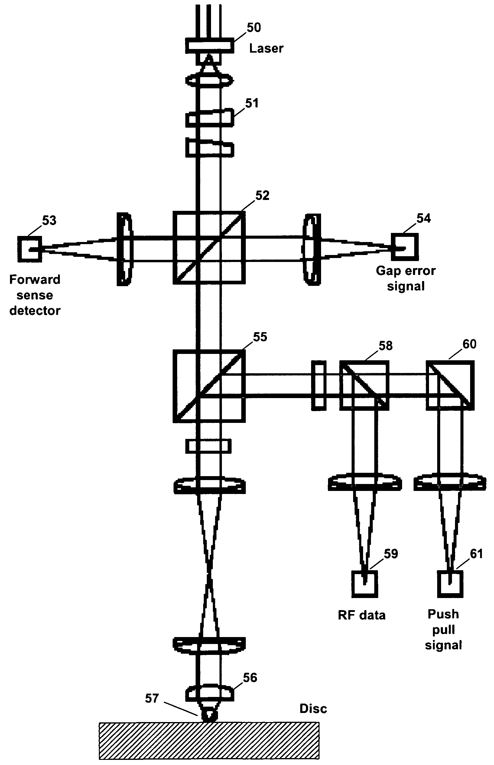
The present invention provides an apparatus and method for stably performing a tracking servo operation in a near field optics. It also removes a dc offset from a one-beam push pull signal in a near field optics. The method compensates a push pull signal using a divided and detected gap error signals detected in a divided state. The apparatus includes a first optical-electric converter for detecting a push pull signal, a second optical-electric converter for detecting gap error signals, and a tracking error detecting unit for compensating the push pull signal detected in the first optical-electric converter using the gap error signals detected in a divided state.

Problems solved by technology

Accordingly, it is difficult to apply the differential push pull scheme to near field recording in which data must be recorded and reproduced in a state where the objective lens is much close to the optical disc.
In addition, as described above, since the dc offset component cannot be removed when the one-beam push pull scheme is applied, an error occurs in the tracking servo operation.

Method used


Image

  • Apparatus and method for controlling tracking servo in near field optics
  • Apparatus and method for controlling tracking servo in near field optics
  • Apparatus and method for controlling tracking servo in near field optics

Examples


Embodiment Construction

[0025]Hereinafter, a preferred embodiment of the present invention will be described with reference to the accompanying drawings. In the following description and drawings, the same reference numerals are used to designate the same or similar components, and so repetition of the description on the same or similar components will be omitted.

[0026]A near field recording technique combines an objective lens with a solid immersion lens, and increases a numerical aperture of the objective lens to be about 2, thereby heightening a recoding density. In order to employ the near field recording technique, a constant distance between the objective lens and a disc must be maintained in a state where the lens is much close to the disc. To this end, it is necessary to employ an additional apparatus.

[0027]In a conventional far-field recording scheme, only a focus servo is sufficient to maintain a constant distance between an objective lens and a disc. However, in the near field recording scheme, ...


PUM

PropertyMeasurementUnit
distanceaaaaaaaaaa
recording densityaaaaaaaaaa
areaaaaaaaaaaa

Abstract

Disclosed are an apparatus and a method for controlling a tracking servo in a near field optics. Gap error signals are detected in a divided state, and a push pull signal is compensated based on the detected gap error signals. A photo detector detecting the gap error signals is divided into two areas such that movement of an image formed on the photo detector can be detected. The push pull signal is compensated by subtracting a value proportional to a difference value between the two gap error signals detected in the photo detector. The difference value between the two gap error signals is proportional to a dc offset component included in the push pull signal. Accordingly, it is possible to simply remove a dc offset included in a push pull signal without largely modifying the near field optics, so that it is possible to exactly perform a tracking servo operation.

Description

BACKGROUND OF THE INVENTION[0001]1. Field of the Invention[0002]The present invention relates to an apparatus and a method for controlling a tracking servo in a near field optics, and more particular to an apparatus and a method for removing a dc offset of a one-beam push pull signal in a near field optics.[0003]2. Description of the Related Art[0004]Digital versatile discs (DVD), which are capable of recording and storing high definition video data and high sound quality audio data with a high capacity, are widely used, and it is expected that blu-ray discs (BD), which have a higher recording density as compared with the DVD, will be developed and commercialized.[0005]The DVD has a storage capacity of about 4.7 GB, and the BD has a storage capacity of about 25 GB. Recently, next generation high definition discs such as a near field recording disc or a near field disc having a recording density much higher than that of the BD are being researched.[0006]The near field disc may be cal...

Claims


Application Information

Patent Timeline
Patent Type & Authority Patents(United States)
IPC IPC(8): G11B7/00
CPCG11B7/0903G11B7/09
Inventor SEO, JEONG KYOSHIN, YUN SUPKIM, JIN YONG
Owner LG ELECTRONICS INC
Learn More