Fluid dynamic bearing mechanism for a motor
a technology of dynamic bearing and motor, which is applied in the direction of sliding contact bearing, record information storage, instruments, etc., can solve the problems of small and thin fluid bearings, and achieve the effects of easy checking of the amount of lubricant, low cost, and high bearing rigidity and rotating accuracy
- Summary
- Abstract
- Description
- Claims
- Application Information
AI Technical Summary
Benefits of technology
Problems solved by technology
Method used
Image
Examples
embodiment 1
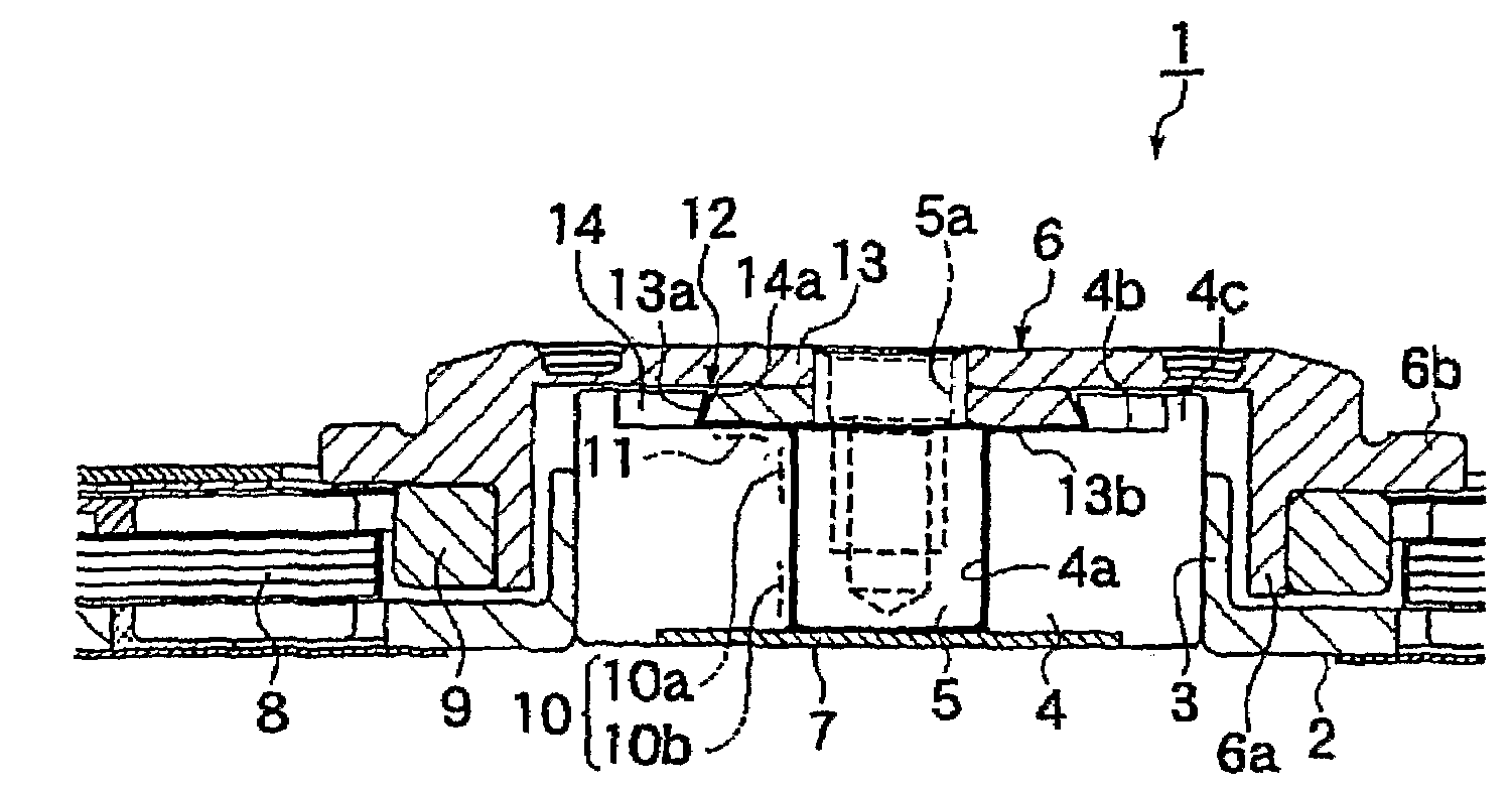
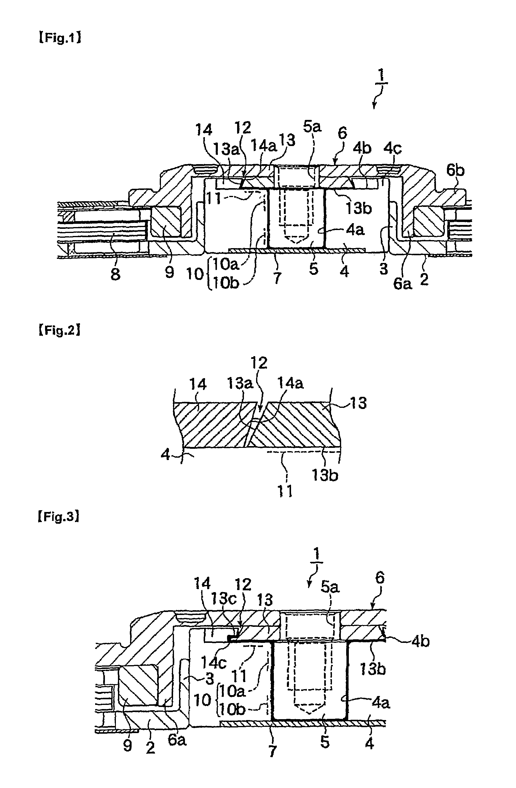
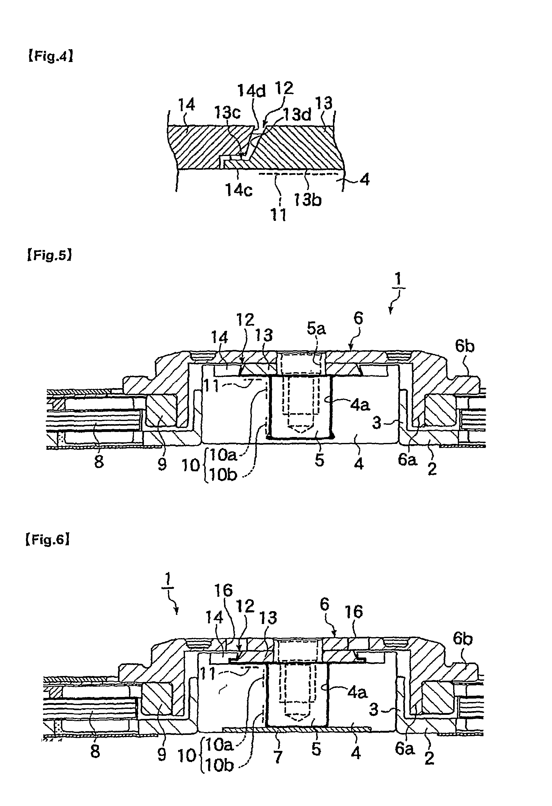
[0040]FIG. 1 is a vertical cross section of a motor 1 of Embodiment 1 and FIG. 2 is an enlarged view of a portion of FIG. 1. In Embodiment 1, the motor 1 is a spindle motor used to drive a hard disk drive. A cylindrical bearing holding member 3 provided vertically in the center of a base member 2 has mounted in it a cylindrical sleeve that forms a bearing member 4 of a fluid dynamic bearing mechanism. A bearing hole 4a formed in the center of the bearing member (sleeve) 4 rotatably supports a shaft member (shaft) 5 that functions as the rotating shaft.
[0041]An upper-direction reduced diameter end of shaft member 5 is fitted with a rotor member (rotor hub) 6 that rotates carrying a disk (not shown). The disk is mounted on the surface of a flange part 6b of rotor member 6 and is affixed on rotor member 6 by means of a clamp member (not shown). A screw hole 5a is formed on an end of shaft member 5 for fastening the clamp member and the rotor member 6 onto the shaft member 5 by a screw....
embodiment 2
[0053]The second embodiment (Embodiment 2) of the present invention will be described below.
[0054]FIG. 3 is a vertical cross section of a motor 1 of Embodiment 2 and FIG. 4 is an enlarged view of a portion of FIG. 3. In Embodiment 2, the structure of the capillary seal part 12 of motor 1 is different from that in Embodiment 1. In Embodiment 2, a step 13c is provided in place of the taper 13a, and a step 14c is provided in place of the taper 14a.
[0055]These steps 13c and 14c are steps formed on the outer periphery surface of annular member on shaft member side 13 and the inner periphery surface of annular member on bearing member side 14 in the inward radial direction. Normally only one step is formed on these surfaces. The radial gap between a one half outer periphery surface portion 13d on one end in the axial direction of the step 13c (upper side in FIG. 3) and a one half inner periphery surface portion 14d on one end in the axial direction of the step 14c can be arranged either ...
embodiment 3
[0063]The third embodiment (Embodiment 3) of the present invention will be described below.
[0064]FIG. 5 is a vertical cross section of a motor 1 of Embodiment 3. In Embodiment 3, a bearing member 4 and a cover plate 7 that blocks the open end of a bearing hole 4a of the bearing member 4 are made of the same material as an integral part so that the cover plate 7 is not an independent part. Other than that, it is identical to Embodiment 1.
[0065]The construction of Embodiment 3 prevents the leakage of lubricant from the lubricant filling part to the outside almost completely except for the possibility of a slight leakage via the capillary seal part 12. Also, it simplifies the construction of the bearing member 4, reduces the number of components, and can reduce the assembly man-hours.
[0066]The integral structure of the cover plate 7 and bearing member 4 in Embodiment 3 can be applied to all other embodiments that use a cover plate.
PUM
 Abstract
Description
Claims
Application Information
 - R&D
- Intellectual Property
- Life Sciences
- Materials
- Tech Scout
- Unparalleled Data Quality
- Higher Quality Content
- 60% Fewer Hallucinations
Browse by: Latest US Patents, China's latest patents, Technical Efficacy Thesaurus, Application Domain, Technology Topic, Popular Technical Reports.
© 2025 PatSnap. All rights reserved.Legal|Privacy policy|Modern Slavery Act Transparency Statement|Sitemap|About US| Contact US: help@patsnap.com


