Method, system, and program for master and slave units connected in daisy chain wherein appended error code is transferred between the units

a data transfer method and slave unit technology, applied in the direction of coding, code conversion, instruments, etc., can solve the problems of inability to transfer data at high speed, data transfer speed tends to be lowered, and maintenance on the machine tool or the robot can be improved, and the speed of data transfer is high

Active Publication Date: 2010-01-26
FANUC LTD
View PDF8 Cites 0 Cited by
  • Summary
  • Abstract
  • Description
  • Claims
  • Application Information

AI Technical Summary

Benefits of technology

[0010]In view of the above-described problem, it is an object of the present invention to provide a data transfer method and a data transfer apparatus that is capable of performing high speed data transfer between slave units connected by a daisy chain system, and is capable of identifying the slave unit where a data error has occurred.
[0012]In accordance with this invention, since data with error check code or error correction code are transferred from the data transmitter to the data receiver without performing error check at the slave unit, it is possible to transfer data at high speed between a plurality of slave units connected to a daisy chain. Since error check of data with error check code or error correction code is performed in a separate circuit aside from the circuit through which the data with error check code or error correction code flow in the slave unit, the slave unit in which the error has occurred can be identified without lowering the data transfer speed of data transferred from the data transmitter to the data receiver. Since the result of the error check is individually sent to the master unit, the slave unit in which the error has occurred can be recognized via the master unit. Therefore, data can be transferred at high speed, the slave unit in which the error has occurred can be identified so that maintenance for the machine tool or the robot can be improved.
[0014]In accordance with this invention, the data with error check code or error correction code can be transferred by the data transfer portion without performing error check or error correction, high speed data transfer is possible between a plurality of slave units connected by the daisy chain system. Also, error check of the data with error check code or error correction code can be performed by the error check portion in a circuit provided in the slave unit aside from the circuit through which the data with error check code or error correction code flow, and the slave unit in which the error has occurred can be thereby identified. With the error informing portion with which said slave unit informs the result of the error check to the master unit, the slave unit in which the error has occurred can be recognized via the master unit. Therefore, data transfer can be carried out at high speed, the slave unit in which the error has occurred can be identified and maintenance on the machine tool or the robot can be improved.

Problems solved by technology

However, with such a data transfer method, there is a problem that, when data having the appended error check code or data having the appended error correction code are to be transmitted from downstream individual slave units to the upstream side, the data transfer speed tends to be lowered.
With this method, data cannot be transferred to the upstream side until all of the data has been received, and this makes it impossible to transfer data at high speed.
However, in the example shown in FIG. 8, there is a problem in that error information from individual slave units 53 cannot be obtained from data having the appended error check code or error correction code received by the master unit 52, and it is impossible to identify the slave unit 53 where the error has occurred.
In the example shown in FIG. 9, there is also a problem in that error information cannot be obtained from data 51 having the appended error check code or error correction code transmitted by the master unit 52 and received by a receiving slave unit 53, connected to the serial bus from the data transmitter to the data receiver, and it is impossible to identify the slave unit where the error has occurred.
Therefore, when performing maintenance on the machine tool or the robot which is shut down by an error in control data caused by noise or fault, it takes a lot of time to detect the noise source or locate the fault, and maintenance cost may be increased due to unnecessary replacement of parts.

Method used


Image

  • Method, system, and program for master and slave units connected in daisy chain wherein appended error code is transferred between the units
  • Method, system, and program for master and slave units connected in daisy chain wherein appended error code is transferred between the units
  • Method, system, and program for master and slave units connected in daisy chain wherein appended error code is transferred between the units

Examples


Embodiment Construction

[0025]A data transfer apparatus according to the present invention will now be described in detail below with reference to the drawings. In the drawings, common constituents are denoted by the same reference numerals or symbols and duplicate explanation thereof is omitted.

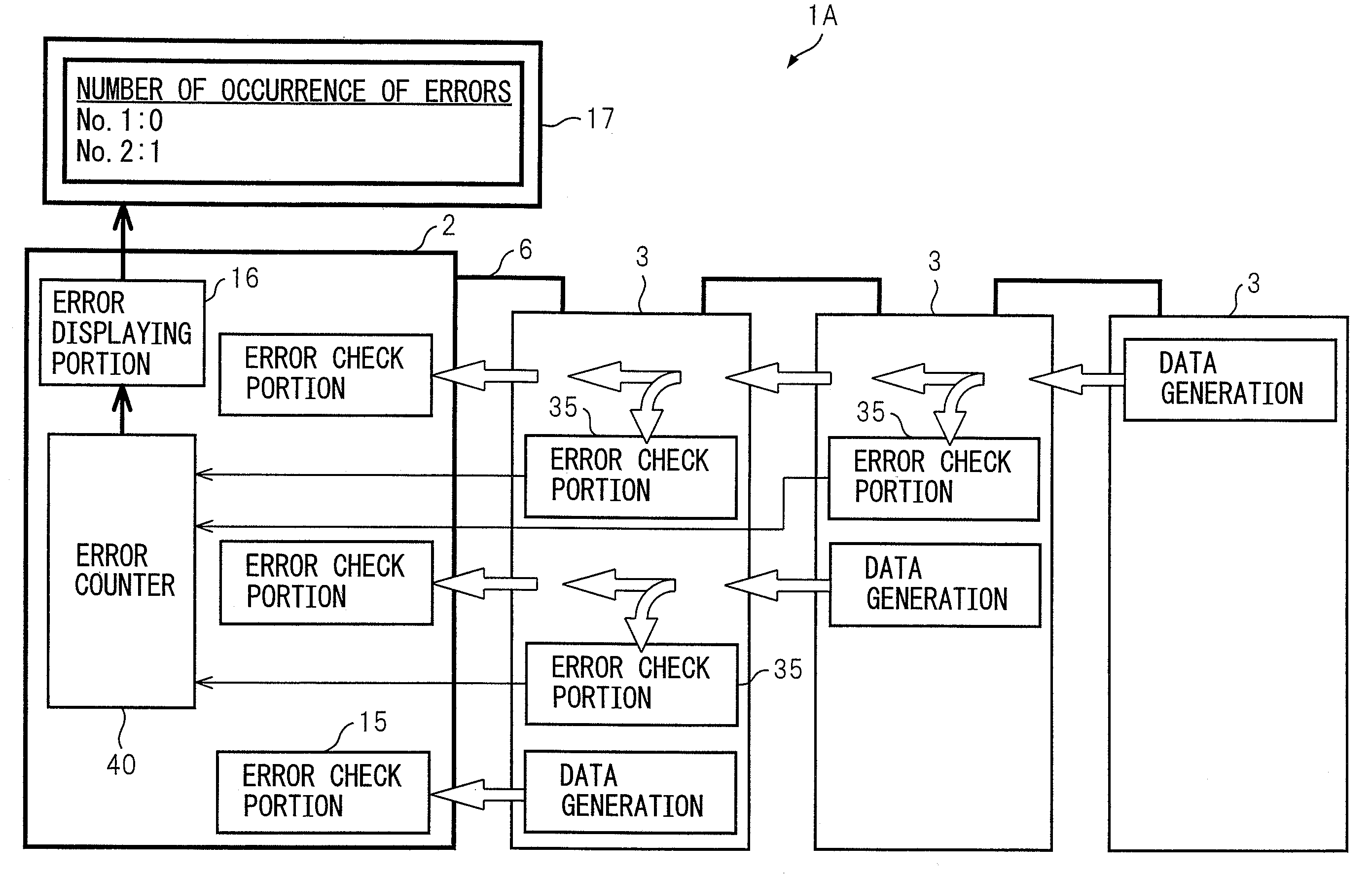
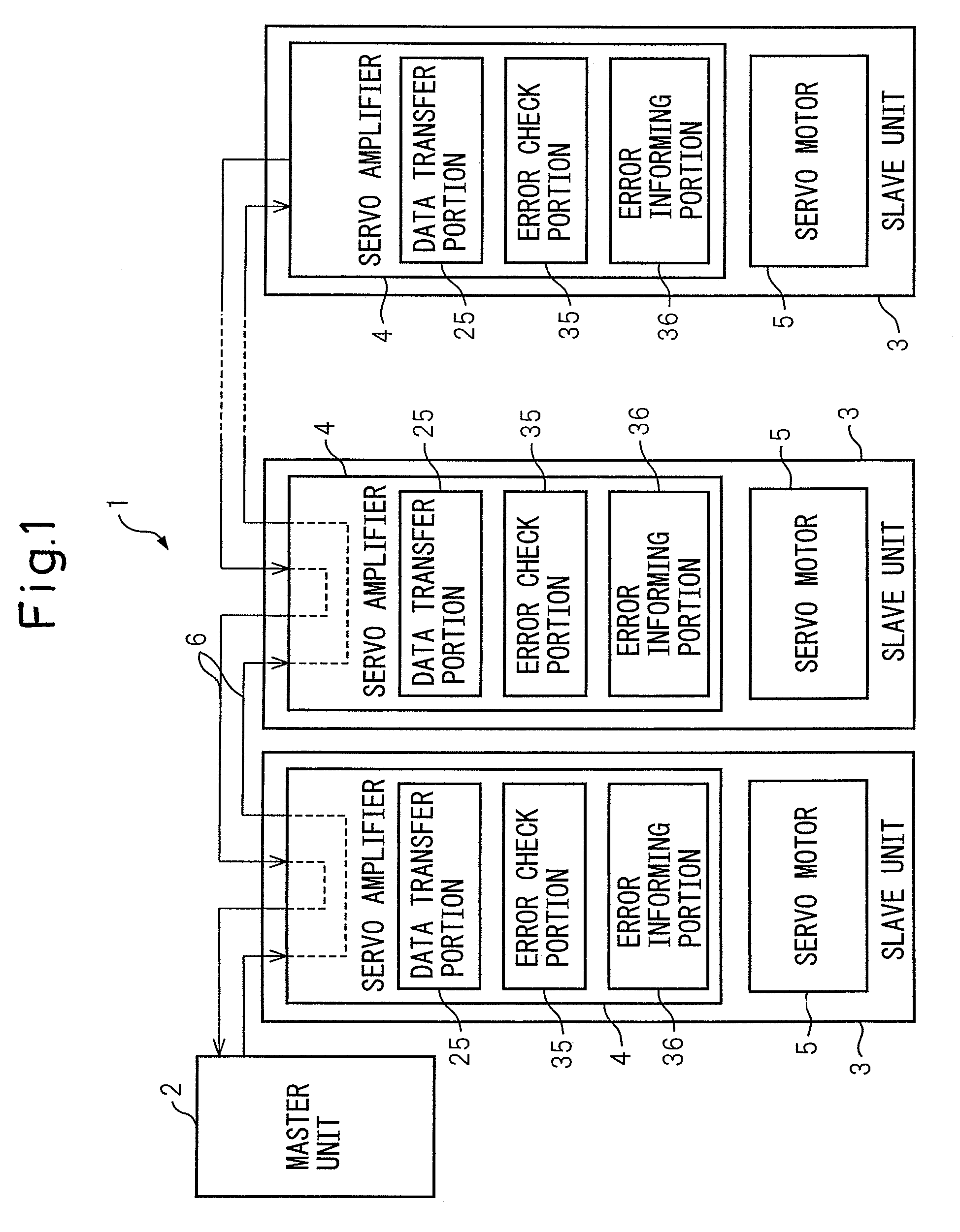
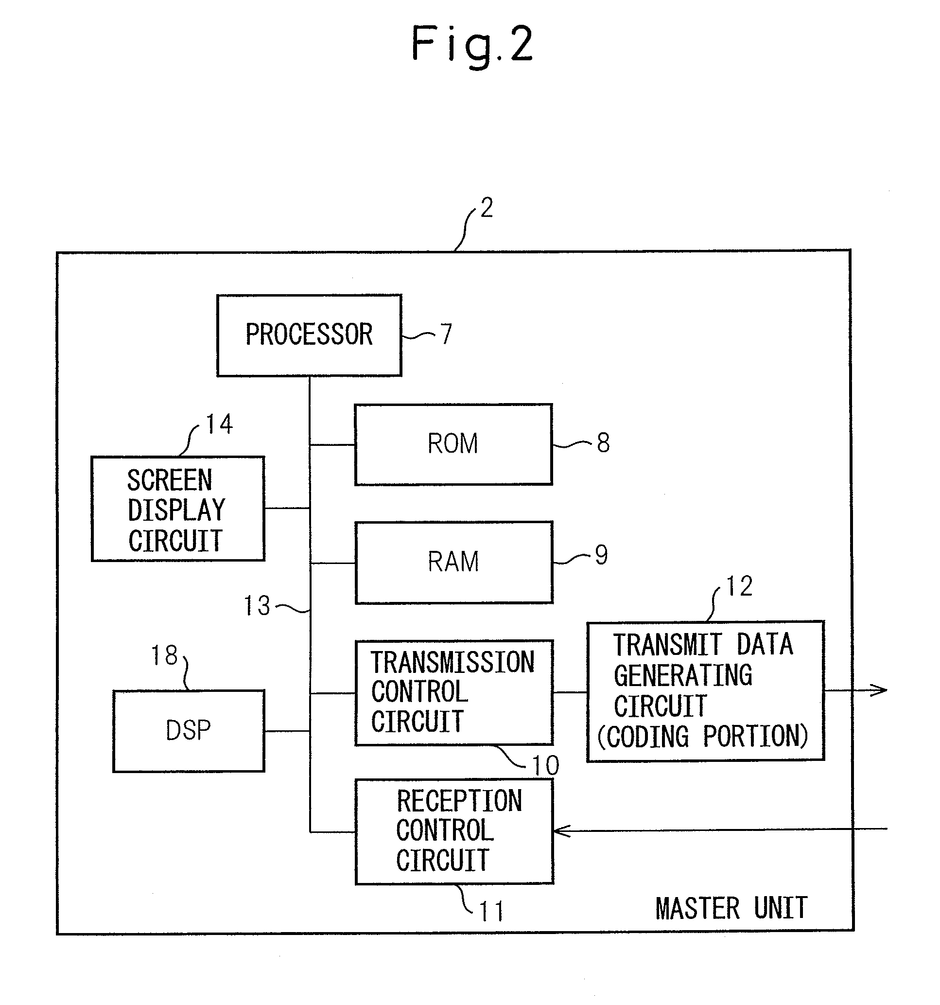
[0026]As shown in FIG. 1, a data transfer apparatus 1 according to the present embodiment comprises a master unit 2 as a control apparatus situated on an upstream side and a plurality of slave units 3 situated on a downstream side. Each of the slave units 3 comprises a servo amplifier 4 and a servo motor 5. The master unit 2 and a plurality of slave units 3 are connected in series by a daisy chain system with serial bus, such that data can be transferred in both directions between the master unit 2 and the slave unit 3 on the downstream side. Thus, servo motors 5 are controlled and driven by the control data transferred from the master unit 2 to the slave units 3 (from upstream side to downstream side), and the sta...


PUM


Abstract

A data transfer method for connecting a master unit on an upstream side and a plurality of slave units on an downstream side in series with serial bus by a daisy chain system and transferring data having an appended error check code or error correction code between a data transmitter and a data receiver, the data transfer method including: transferring the data flowing in the serial bus in the slave unit from the data transmitter to the data receiver without performing an error check or error correction; performing an error check of the data in a circuit provided in the slave unit aside from a circuit in which the data flow; and informing a result of the error check to the master unit individually by the slave unit, which has performed the error check of the data.

Description

CROSS REFERENCE TO RELATED APPLICATIONS[0001]The present application claims priority based on Japanese Patent Application No. 2006-228053 filed on Aug. 24, 2006, the disclosure of which is incorporated herein in its entirety by reference.BACKGROUND OF THE INVENTION[0002]1. Field of the Invention[0003]The present invention relates to a data transfer method and a data transfer apparatus for making a robot perform desired operations in various driving axes in synchronism with each other.[0004]2. Description of the Related Art[0005]Generally, as a data transfer method for operating various axes of a machine tool or a robot in synchronism with each other, there is a known data transfer method in which a master unit, such as a controller situated on an upstream side and slave units, such as a plurality of servo amplifiers situated on a downstream side are connected in series by a daisy chain system with a serial bus, and data having an appended error check code or data having an appended ...

Claims


Application Information

Patent Timeline
Patent Type & Authority Patents(United States)
IPC IPC(8): G06F3/00
CPCH04L1/0045H04L1/245H04L2001/0094H04L2001/0097
Inventor AOYAMA, KAZUNARIKOMAKI, KUNITAKAMIURA, MASAHIRO
Owner FANUC LTD
Why Eureka
Try Eureka