
Image reconstruction method and tomograph

a reconstruction method and image technology, applied in tomography, instruments, nuclear engineering, etc., can solve the problems of discontinuity in image quality, difficult to perform the correction of redundancy on imaging data without a complicated procedure, and difficult to achieve weight slope, reduce the influence of movement, and improve the effect of results

Active Publication Date: 2010-01-26
FUJIFILM HEALTHCARE CORP
View PDF13 Cites 8 Cited by
  • Summary
  • Abstract
  • Description
  • Claims
  • Application Information

AI Technical Summary

Benefits of technology

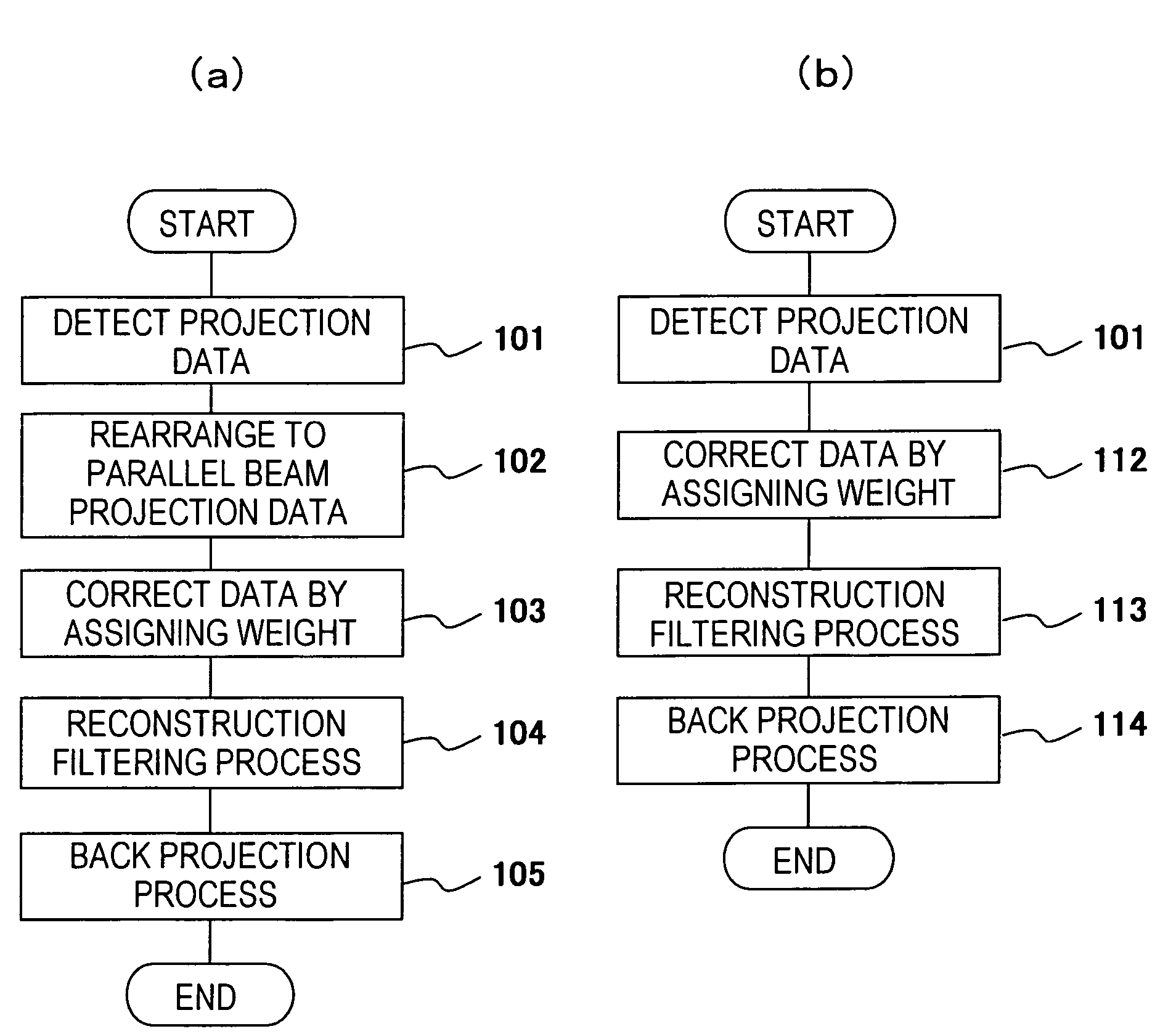
The present invention provides an improved tomogram reconstruction method that addresses various problems with conventional methods, such as difficulty in achieving the desired image quality, the occurrence of image blurring due to bio-movement, and the difficulty in adjusting the trade-off between reducing image noise and shortening the imaging time. The method uses a weighting function that takes into account the correction angle width and the projection data angle using for back-projection, allowing for a more accurate and efficient reconstruction of tomograms. The method also allows for the adjustment of the weighting function based on the correction angle width and the projection data angle using for back-projection, as well as the setting of the correction angle width and the projection data angle using for back-projection to be the same or different. The method further includes a step for rearranging the fan beam to improve the quality of the tomogram.

Problems solved by technology

As described above, with a conventional tomograph presents a difficulty to achieve the reconstruction in the projection data angle using for back-projection and also the problem that the discontinuity of the image is generated when the projection data angle using for back-projection is more than 2π.
It is also difficult to perform the correction of redundancy on the imaging data without a complicated procedure.
A further problem with the conventional tomograph is the deterioration of image quality by discontinuity due to the movement of the object being examined, and the difficulty in adjusting the trade-off relationship between reducing the amount of image noise and shortening the imaging time.

Method used


Image

  • Image reconstruction method and tomograph
  • Image reconstruction method and tomograph
  • Image reconstruction method and tomograph

Examples


embodiments

[0159]In order to compare the conventional reconstruction methods using a weighting function and the reconstruction method of the present invention, motion artifacts and the image SD value were obtained and evaluated. As for the geometry, the one of the cone beam was adopted.

[0160][Simulation 1]

[0161]The image was reconstructed using the weight being created by fixing the index of projection data angle using for back-projection as F=1.1 and varying correction angle width index ε as 0.0, 0.2, 0.4, 0.6, and the generation of motion artifacts was verified. The weighting function shape and the reconstructed images are shown in FIG. 12. In the case of correction angle width ε=0 as shown in FIG. 12 (a), an intensive motion artifact appears since the slope of the weight is not maintained. In the case of ε=0.2 shown in (b) which is comparable to the conventional weight, some improvement can be recognized, yet it is still insufficient. On the other hand, a considerable improvement of motion ...


PUM


Abstract

A weighting function is created according to an arbitrary bio-movement correction range and a projection data angle for back-projection (width in the view direction used for reconstruction), set by a user, by considering the degree of the bio-movement and redundancy. By using this weighting function, an image reconstruction is performed.The bio-movement correction range is set as a correction angle width index ε expressing the width guaranteed as a slope portion of the weighting function. The projection data angle for back-projection (data width) is determined by considering the data redundancy, SN, time width (time resolution) contributing to the image.By determining the weight according to these two parameters, it is possible to apply reconstruction of projection data of all the scan ranges in the reconstruction of the tomogram and prevent lowering of the data contribution ratio as well as reduce the motion artifact, thereby obtaining a high-quality image.

Description

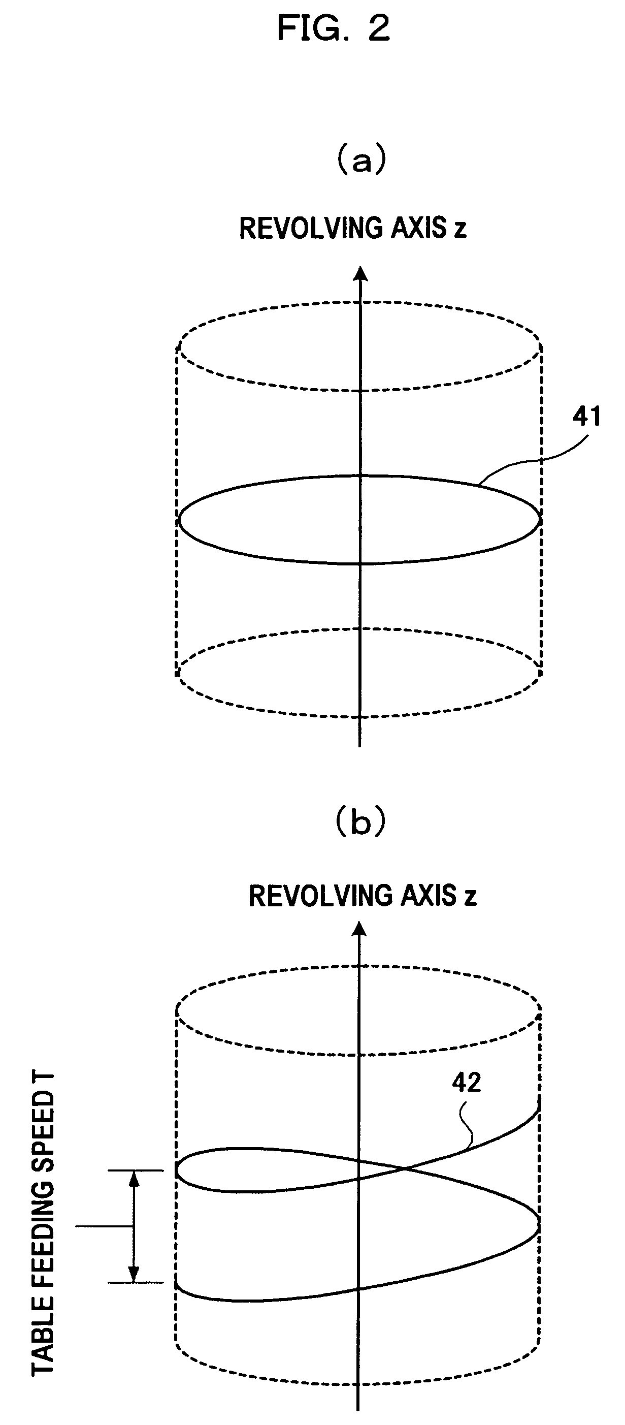
TECHNICAL FIELD[0001]The present invention relates to a method for reconstructing a tomogram from a projection data in a computerized tomograph (hereinafter referred to as CT apparatus) using a fan beam or cone beam, more particularly to a method to reconstruct a tomogram from projection data having more than π [rad] of projection data angle using for back-projection and a CT apparatus to achieve the objective of the method thereof.BACKGROUND ART[0002]An X-ray CT apparatus acquires projection data by receiving an X-ray radiated from an X-ray source and transmitted through an object being examined, with an X-ray detector disposed on the opposite side of the X-ray source interposing the object therebetween. Upon acquiring the projection data, the X-ray source and the X-ray detector disposed to be opposite to each other interposing the object therebetween are revolved around revolving axis, and the projection data in different angles of rotation (phase) are collected. By reconstructing...

Claims


Application Information

Patent Timeline
Patent Type & Authority Patents(United States)
IPC IPC(8): G06K9/00A61B6/03G06T11/00
CPCG06T11/006A61B6/032A61B6/027G06T2211/421G06T2211/412
Inventor GOTO, TAIGAMIYAZAKI, OSAMUHIROKAWA, KOICHI
Owner FUJIFILM HEALTHCARE CORP
Learn More