
Semiconductor device

a technology of semiconductor devices and shielding rings, applied in semiconductor devices, semiconductor/solid-state device details, electrical devices, etc., can solve problems such as blockage regions not always provided along the sealing ring, and failure to meet the requirements of sealing ring requirements, so as to achieve the effect of suppressing noise transmission

Active Publication Date: 2010-01-26
RENESAS ELECTRONICS CORP
View PDF3 Cites 8 Cited by
  • Summary
  • Abstract
  • Description
  • Claims
  • Application Information

AI Technical Summary

Benefits of technology

The present invention provides a semiconductor device with a blocking region to suppress noise transmission between different device regions. The blocking region is formed on a semiconductor substrate and includes a well. The blocking region prevents noise from reaching the second device region through the seal ring and insulating interlayer. The invention also provides a method for forming the blocking region to further improve its effectiveness. The technical effect of the invention is to suppress malfunctions caused by noise transmission between different device regions and improve the reliability of the semiconductor device.

Problems solved by technology

Generally, however, the seal ring is electrically connected to a semiconductor substrate, so that noise that is apt to be generated in the device region of a digital circuit chip or the like is often transmitted to another device region through the seal ring, thereby causing malfunction of the elements provided in another region.
As described above, noise generated in a predetermined device region is transmitted to another device region through a seal ring, thereby causing malfunction of an element provided in another device region sometimes.
However, the blocking region may not always be provided along the seal ring.

Method used


Image

  • Semiconductor device
  • Semiconductor device
  • Semiconductor device

Examples


first embodiment

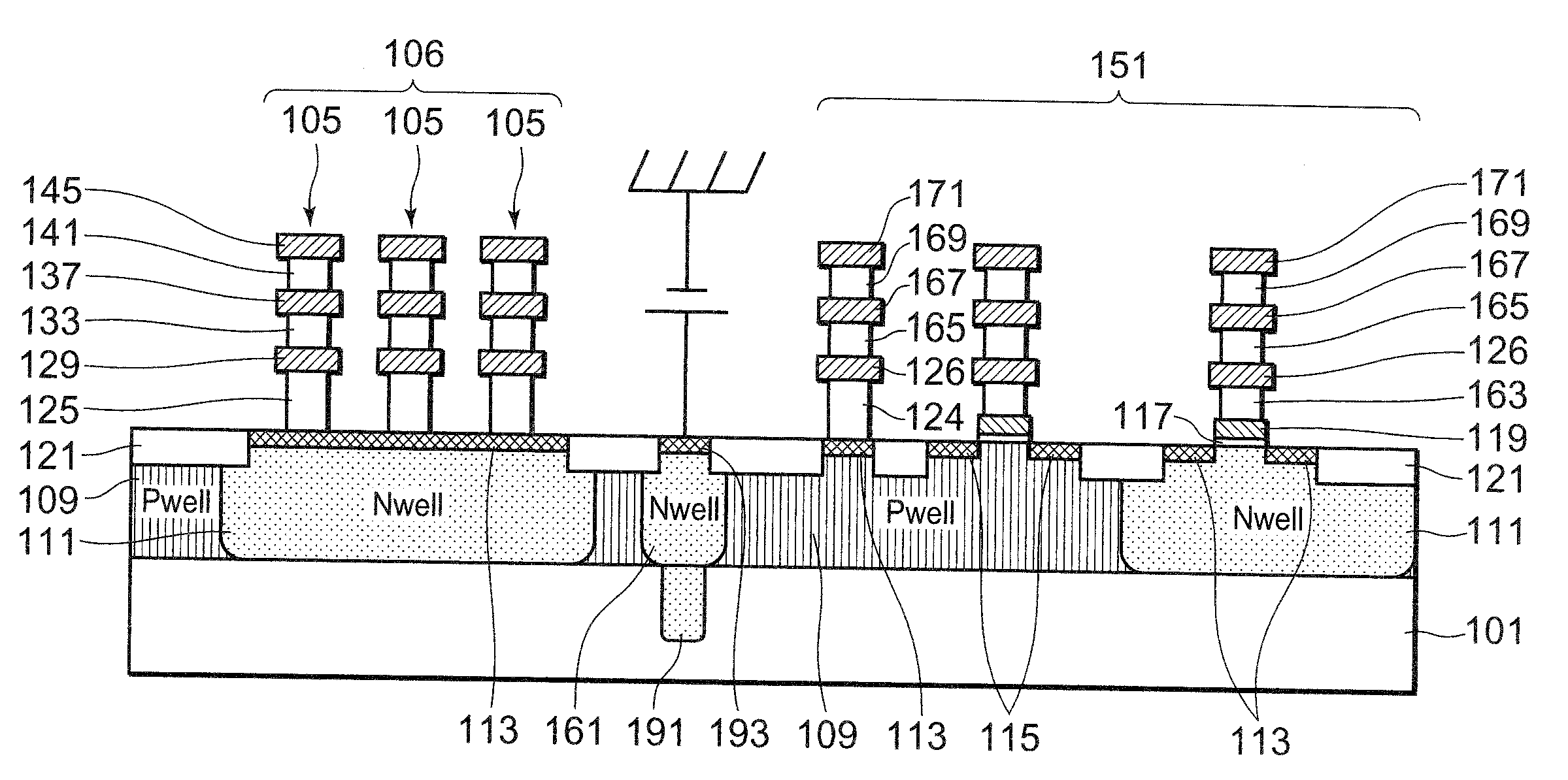
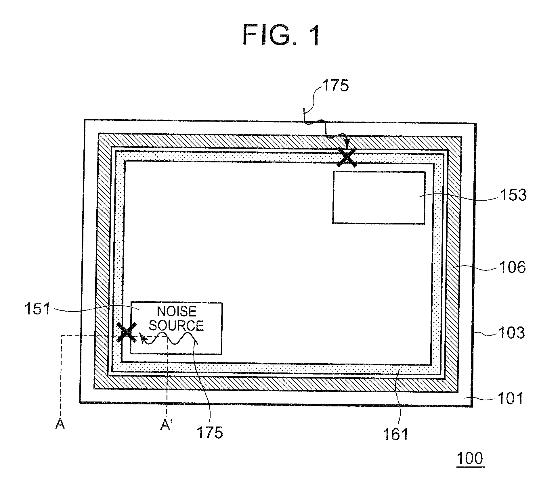
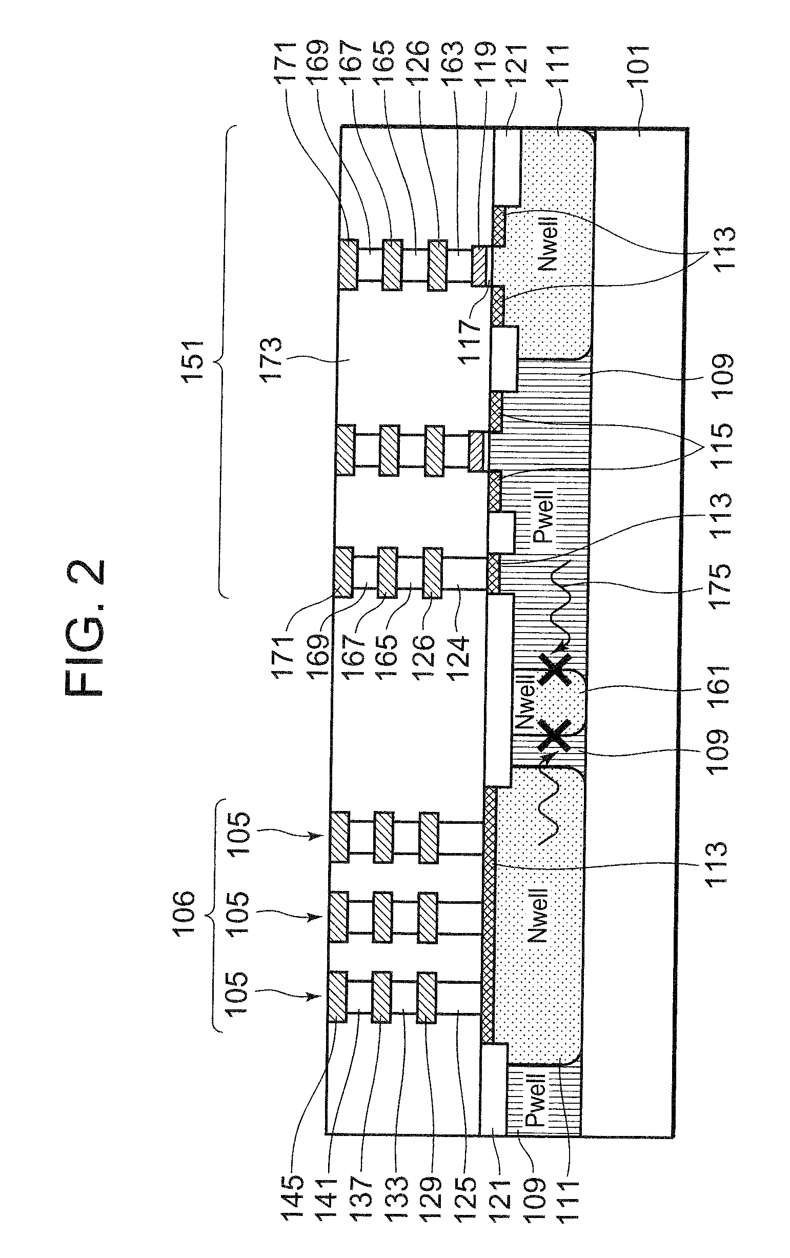
[0045]FIG. 1 shows a schematic top view of a configuration of a semiconductor device in this first embodiment. FIG. 2 shows a cross sectional view taken on line A-A′ of the semiconductor device 100 shown in FIG. 1. In FIG. 2 is shown a configuration of a seal ring region 106 and an internal circuit of a logic unit 151 provided inside the seal ring region 106. The cross section of an analog unit 153 is the same as, for example, that of the logic unit 151.

[0046]The semiconductor device 100 shown in FIGS. 1 and 2 respectively includes a first device region (logic unit 151) and a second device region (analog unit 153). The logic unit 151 is device region that might become a source of noise 175 and the analog unit 153 is a device region that might become a damaged circuit.

[0047]The semiconductor device 100 includes a semiconductor substrate (silicon substrate 101), an insulating interlayer 173 provided on the silicon substrate 101, and a conductive film buried in the insulating interlaye...

second embodiment

[0082]In the semiconductor device 100 in the first embodiment, the noise blocking region is constituted by one N well guard ring 161. However, the number of N well guard rings is not limited especially in this second embodiment; for example, plural N well guard rings may be disposed in a concentric pattern in the plane of the substrate. Hereunder, there will be described this second embodiment that will take such a configuration.

[0083]FIG. 3 shows a cross sectional view of a configuration of a semiconductor device in this second embodiment. Basically, the configuration is the same as that of the semiconductor device shown in FIG. 2 except that a first N well guard ring 177, a second N well guard ring 179, and a third N well guard ring 181 are provided instead of the N well guard ring 161. Also in this second embodiment, the cross sectional configuration of the analog unit 153 is the same as, for example, that of the logic unit 151.

[0084]Each of the first N well guard ring 177, the s...

third embodiment

[0090]FIG. 5 shows a cross sectional view of a configuration of a semiconductor device in this third embodiment. Basically, the configuration of the semiconductor device shown in FIG. 5 is the same as that shown in FIG. 2 except that the N well guard ring 161 that constitute a blocking region is fixed at a predetermined potential. In FIG. 5, the N+ diffusion layer 193 is provided near the surface of the silicon substrate 101 over the N well guard ring 161. In FIG. 5, the insulating interlayer 173 is omitted. Also in this third embodiment, the cross sectional configuration of the analog unit 153 is the same as, for example, that of the logic unit 151.

[0091]The N+ diffusion layer 193 may be formed over the forming region of the N well guard ring 161 entirely. It is also possible to form the layer 193 in part of the N well guard ring forming region. The planar shape of the N+ diffusion layer 193 may also be changed to, for example, a ring-like shape. The outer periphery of a side surfa...


PUM


Abstract

A semiconductor device that can suppress noise transmission through a seal ring provided between two device regions. The semiconductor device includes a logic unit and an analog unit. The semiconductor device further includes a silicon substrate, an insulating interlayer, a seal ring surrounding the outer periphery of the logic unit composed of a conductive film buried in the insulating interlayer, a well provided on the silicon substrate, and an N well guard ring that blocks conduction of a path from the logic unit, through the seal ring to the analog unit. The N well guard ring is disposed between the seal ring region 106 and the logic unit or the analog unit.

Description

BACKGROUND OF THE INVENTION[0001]1. Field of the Invention[0002]The present invention relates to a semiconductor device and more particularly to a semiconductor device having plural device regions and seal ring.[0003]2. Description of Related Art[0004]In order to protect a circuit-forming region in a semiconductor chip effectively from moisture, a protective structure referred to as a “seal ring” is provided so as to surround the semiconductor device (chip). The seal ring is formed with a wiring layer as in the circuit-forming region and a via (or contact).[0005]Generally, however, the seal ring is electrically connected to a semiconductor substrate, so that noise that is apt to be generated in the device region of a digital circuit chip or the like is often transmitted to another device region through the seal ring, thereby causing malfunction of the elements provided in another region.[0006]Japanese Unexamined Patent Application Publication No. 2006-147668 discloses a conventional...

Claims


Application Information

Patent Timeline
Patent Type & Authority Patents(United States)
IPC IPC(8): H01L29/00
CPCH01L23/564H01L23/585H01L27/0203H01L27/092H01L2924/0002H01L2924/3011H01L2924/00
Inventor UCHIDA, SHINICHI
Owner RENESAS ELECTRONICS CORP
Learn More