
Vehicle drive control apparatus and method

a technology of drive control and control apparatus, which is applied in the direction of electric propulsion mounting, transportation and packaging, gearing, etc., can solve the problems of falling in the durability of the associated electric circuit that controls the motor generator, so as to achieve the effect of falling in the durability of the associated electric circuit and the quick fluctuation of the wheel speed

Inactive Publication Date: 2010-01-26
NISSAN MOTOR CO LTD
View PDF30 Cites 26 Cited by
  • Summary
  • Abstract
  • Description
  • Claims
  • Application Information

AI Technical Summary

Benefits of technology

The present invention provides a vehicle drive control apparatus and method for a wheeled vehicle that can control the slip state of the drive wheel without falling in durability of the associated electric circuit. The apparatus includes a planetary gear set and rotation control mechanism for selectively establishing a fixed speed ratio mode or a variable speed ratio mode based on the slip state of the drive wheel. The control means is also configured to detect the slip state of the drive wheel and release the rotation control mechanism to establish the variable speed ratio mode when the slip state is detected in the fixed speed ratio mode. This ensures that the vehicle drive control apparatus can control the slip state of the drive wheel without causing damage to the associated electric circuit.

Problems solved by technology

While an ABS or TCS operates, a lock state or slip state and a grip state of associated wheels are repeatedly shifted to each other within a short period of time by the control of the slip ratio of the wheels, resulting in quick fluctuation in each wheel speed.
This may result in a fall in the durability of an associated electric circuit that controls the motor generators.

Method used


Image

  • Vehicle drive control apparatus and method
  • Vehicle drive control apparatus and method
  • Vehicle drive control apparatus and method

Examples


Embodiment Construction

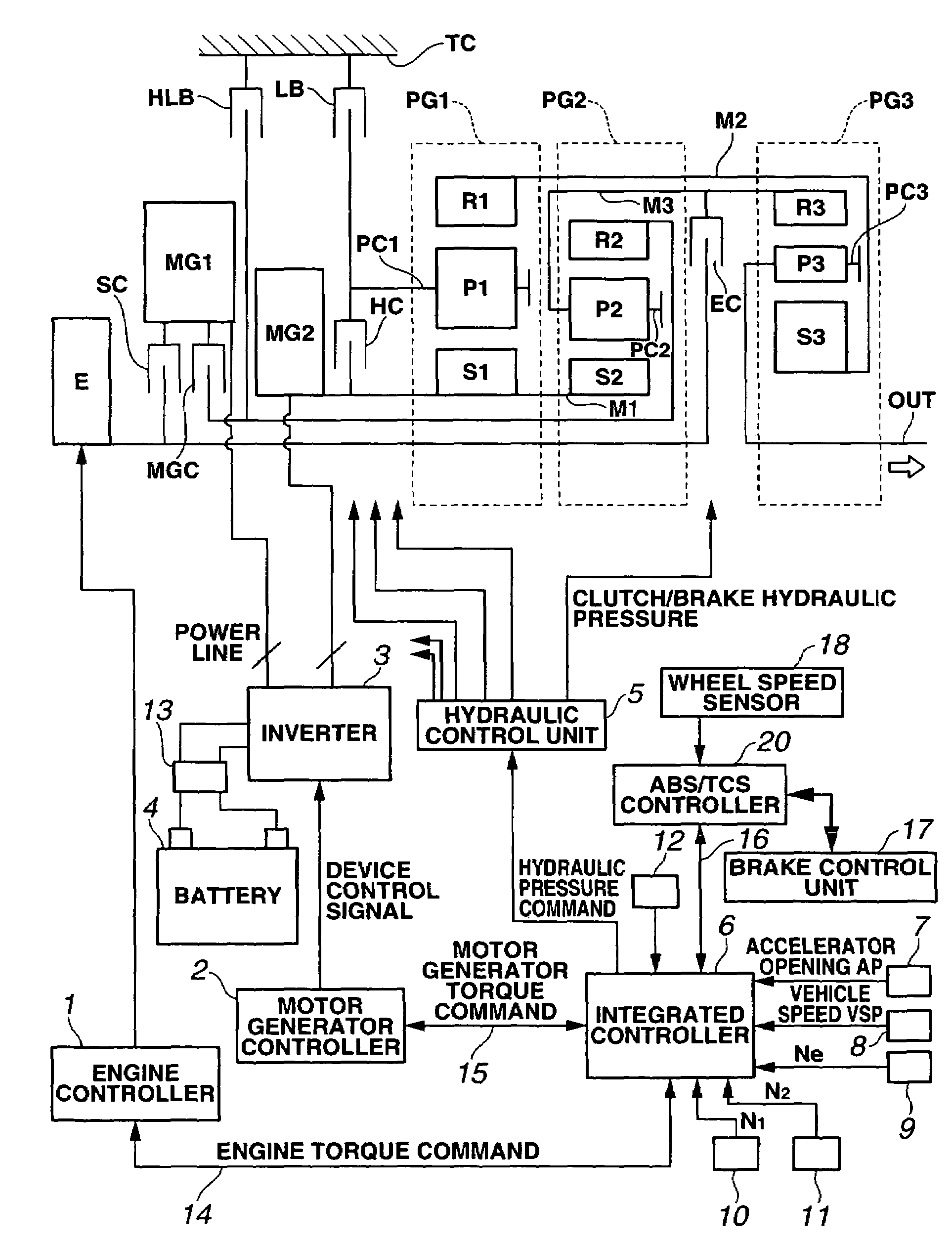
[0033]FIGS. 1 to 23F show a vehicle drive control apparatus in accordance with a first embodiment of the present invention. First, the following describes a drive system of a hybrid electric vehicle in which the vehicle drive control apparatus of the first embodiment is exemplified.

[0034]FIG. 1 is a schematic diagram showing a hybrid electric vehicle including a vehicle drive control apparatus in accordance with a first embodiment of the present invention. As shown in FIG. 1, the drive system of the hybrid electric vehicle comprises an engine E; a first motor generator (generator) MG1; a second motor generator (motor generator) MG2; an output shaft (output member) OUT; a differential gear unit or planetary gear set (a first planetary gear PG1, a second planetary gear PG2, and a third planetary gear PG3) for interconnecting the input / output elements E, MG1, MG2, and OUT; frictional engaging elements (rotation control mechanisms), i.e. a LOW-mode brake (second brake) LB, a HIGH-mode c...


PUM


Abstract

A vehicle drive control for a wheeled vehicle including a first motor generator, and a second motor generator. A planetary gear set includes a first rotating element connected to the first motor generator, a second rotating element connected to the second motor generator, and a third rotating element connected to a drive wheel. A rotation control mechanism selectively restricts rotation of one of the first and second rotating elements of the planetary gear set to establish a fixed speed ratio mode, and releases the one of the first and second rotating elements to establish a variable speed ratio mode. A control unit is configured to control each operating state of the rotation control mechanism, the first motor generator, and the second motor generator, and configured to establish the variable speed ratio mode when a slip state of the drive wheel is detected in the fixed speed ratio mode.

Description

BACKGROUND OF THE INVENTION[0001]The present invention relates generally to a vehicle drive control apparatus and method, and more particularly to a vehicle drive control apparatus and method for speed shift control for an automotive vehicle operable in at least a fixed speed ratio mode in which a speed ratio of an output to an input is fixed and at least a variable speed ratio mode in which the speed ratio is allowed to vary.[0002]Japanese Published Patent Application No. 2004-150627 (henceforth referred to as “JP2004-150627”) shows a hybrid drive system for an automotive vehicle that has six rotating elements in a below-described speed relationship diagram and interconnects an input from an engine, an output to drive wheels, a first motor generator, and a second motor generator. This hybrid drive system is configured to establish a continuously variable speed ratio mode and a fixed speed ratio mode. In the continuously variable speed ratio mode, the speed ratio of an output to an ...

Claims


Application Information

Patent Timeline
Patent Type & Authority Patents(United States)
IPC IPC(8): B60K17/344B60K6/365B60K6/445B60K6/547B60K17/04B60L50/16B60W10/02B60W10/08B60W10/10B60W10/18B60W20/00F16H3/66F16H3/72F16H59/46F16H61/02F16H63/40F16H63/50
CPCB60K6/445B60K28/165B60W10/02B60W10/08B60W10/115F16H3/728B60L11/12B60W20/15B60K6/365B60K1/02Y10T477/26B60W20/00B60W2520/26F16H2037/088F16H2037/102F16H2037/104F16H2037/106F16H2061/0239F16H2200/201Y02T10/6239B60L2270/145Y10T477/27B60L50/15Y02T10/62Y02T10/7072
Inventor HIRATA, TAKESHIYAMANAKA, TSUYOSHI
Owner NISSAN MOTOR CO LTD
Learn More