
Inclinometer measurement system and method providing correction for movement induced acceleration errors

a technology of inclinometer and measurement system, which is applied in the direction of speed measurement using gyroscopic effects, instruments, surveying and navigation, etc., can solve the problems of acceleration measurement errors, unreliable and unusable sensor output, and unsatisfactory and erroneous output signals

Active Publication Date: 2010-01-19
CATERPILLAR TRIMBLE CONTROL TECH
View PDF8 Cites 35 Cited by
  • Summary
  • Abstract
  • Description
  • Claims
  • Application Information

AI Technical Summary

Benefits of technology

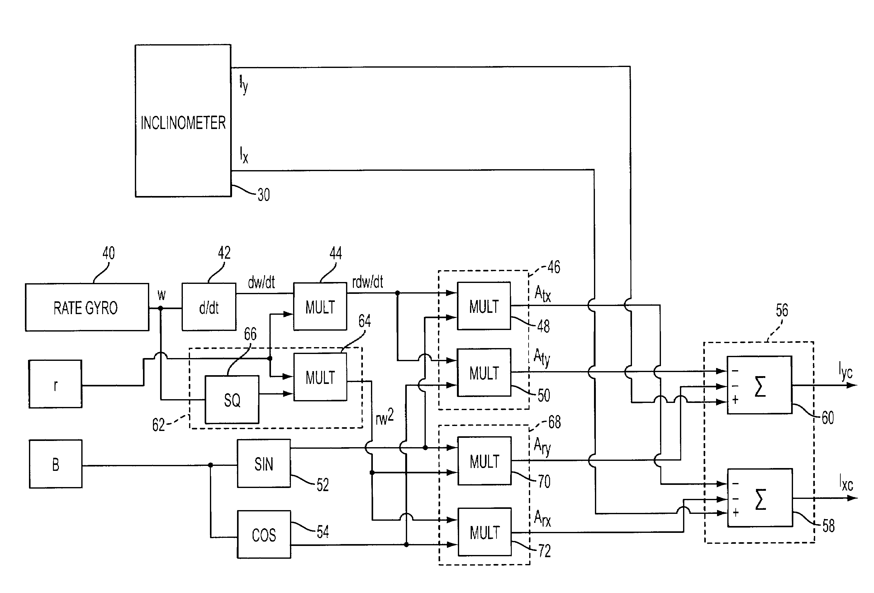
The present invention provides a system and method for sensing the inclination of a platform with respect to gravity. The system includes an inclinometer and a rate gyro mounted on the platform, which provide outputs indicating acceleration in the X and Y directions. A circuit is used to differentiate the rate gyro output to determine the rotational speed of the platform. Another circuit is used to squaren the rotational speed and multiply it by the distance r to determine the radial acceleration of the platform. A method is then used to resolve the tangential acceleration of the platform in the Y axis direction and determine the X and Y axis components of the acceleration. These components are then subtracted to correct for errors caused by tangential acceleration. The system and method provide accurate sensing of the platform's inclination with respect to gravity.

Problems solved by technology

This type of sensor is inherently sensitive to acceleration produced by machine movement, since it cannot distinguish between gravitational acceleration and non-gravitational sources of acceleration.
These non-gravitational sources of acceleration can result in undesired and erroneous output signals from an inclinometer.
In some cases, the undesired signals can be large in comparison to the desired inclination measurement, rendering the sensor output unreliable and unusable until after cessation of the movements that caused this undesired acceleration.
When a movable member is pivoted about an axis, acceleration measurement errors in a radial direction will result from the rotation of the member.
When the speed of this rotation changes, acceleration measurement errors will also result in a direction that is tangential to the direction of movement.
There are practical circumstances in which it is not possible or desirable to locate the inclinometer at the axis about which the member rotates.
When such a gravity referenced inclinometer is not located precisely at the axis about which a movable element on which it is mounted pivots or rotates, it is difficult to obtain an accurate inclination reading.
However, low-pass filtering also introduces latency to the measurement of angle.
Additionally, latency is undesirable in a control system, potentially contributing to system instability.

Method used


Image

  • Inclinometer measurement system and method providing correction for movement induced acceleration errors
  • Inclinometer measurement system and method providing correction for movement induced acceleration errors
  • Inclinometer measurement system and method providing correction for movement induced acceleration errors

Examples


Embodiment Construction

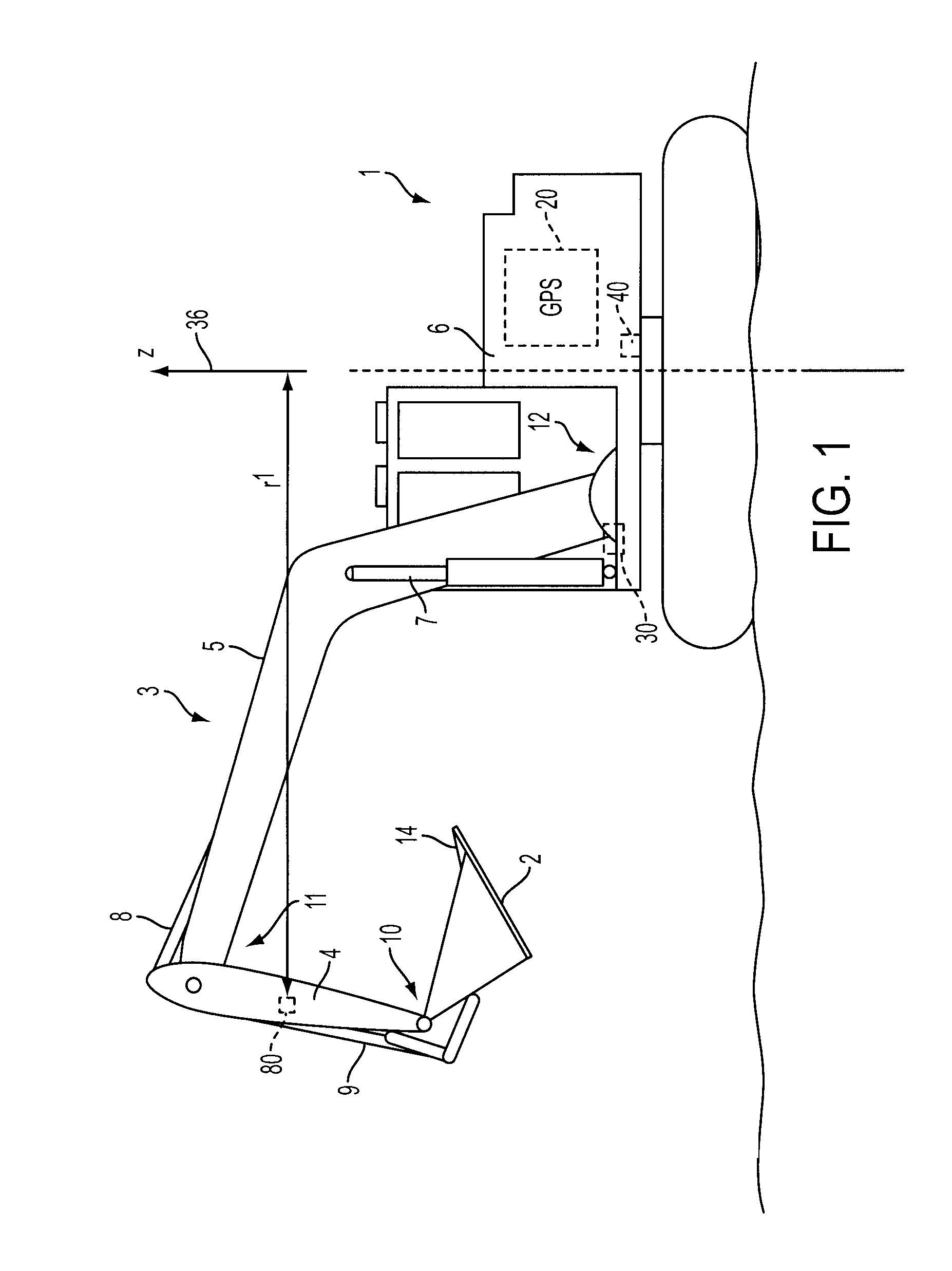
[0019]Reference is made to FIG. 1, which shows an excavator 1 having a positionable tool, such as for example a bucket 2, attached to a tool positioning mechanism 3. The tool positioning mechanism 3 includes a dipper stick 4, and a boom 5 coupled to the cab 6 of the excavator 1. The cab 6 acts as the platform from which the boom 5, dipper stick 4, and bucket 2 may be moved by a series of hydraulic cylinders 7 under operator control, or under control of an on board excavator control system.

[0020]The tool positioning mechanism 3 may include a number of linear or angular position encoders or other similar sensors (not shown), the outputs of which may indicate the orientation and location of the tool positioning mechanism 3 with respect to the cab 6. The encoders may be positioned at various locations along the boom 5, the dipper stick 4, and the bucket 2. The encoders may indicate, for example, the linear positions of linkages and hydraulic cylinders, or the relative angles of pivot po...


PUM


Abstract

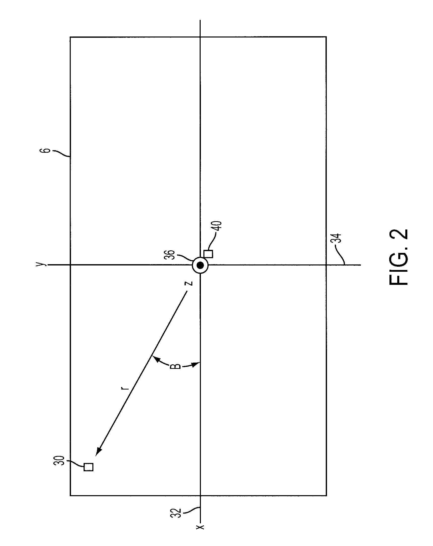
A system and a method sense the inclination of a machine element, such as a platform, and eliminate tangential and radial acceleration errors. The platform defines orthogonal X and Y axes, and is rotatable about a Z axis. An inclinometer, mounted on the platform at a location spaced from the axis of rotation by a distance r, provides inclinometer outputs indicating acceleration in the X and Y directions, Ix and Iy, respectively. A rate gyro on the platform senses the rotational speed w of the platform. The rate gyro output w is differentiated and multiplied by r to determined tangential acceleration at the inclinometer. A circuit resolves the tangential acceleration into X axis and Y axis components, which are used to correct the inclinometer outputs Ix and Iy for errors that would otherwise result from tangential acceleration.

Description

CROSS-REFERENCE TO RELATED APPLICATION[0001]Not applicable.STATEMENT REGARDING FEDERALLY SPONSORED RESEARCH OR DEVELOPMENT[0002]Not applicable.BACKGROUND OF THE INVENTION[0003]The present invention relates to an arrangement for correcting measurement errors produced by movement induced acceleration in a gravity referenced inclination sensor, or inclinometer. It is often desired to know the angle of inclination of a movable member of a machine with respect to the gravity of the earth or with respect to other machine elements. One method to accomplish this is to attach gravity referenced inclinometers to the movable member or elements. The present invention provides a means of improving the performance of such inclinometers during those times when the movable member rotates. The present invention corrects for the effects of tangential and rotational acceleration on inclinometer measurements made with inclinometers that sense acceleration due to gravity.[0004]It is particularly useful ...

Claims


Application Information

Patent Timeline
Patent Type & Authority Patents(United States)
IPC IPC(8): G01C17/38G01C9/08
CPCG01C9/00G01C21/16G01C9/08
Inventor DOUGLAS, FRANK BEARD
Owner CATERPILLAR TRIMBLE CONTROL TECH
Learn More