
System for deicing the nose cone of an aircraft turbojet with oil

a technology for aircraft and turbojets, applied in the direction of efficient propulsion technologies, mechanical devices, machines/engines, etc., can solve the problems of unnecessary provision of means for starting and stopping the deicing system, and achieve the effect of high viscosity of oil

Active Publication Date: 2010-01-19
SN DETUDE & DE CONSTR DE MOTEURS DAVIATION S N E C M A
View PDF9 Cites 17 Cited by
  • Summary
  • Abstract
  • Description
  • Claims
  • Application Information

AI Technical Summary

Benefits of technology

The present invention is a system for deicing the nose cone of an aircraft turbojet that solves the problems of air bleed and reduced efficiency caused by air bleeds from the compressor. The system includes a feed tube, a skin lining the wall of the engine nose cone, radial oil-return tubes, and a centrifugal scoop. The oil flows through the system without the need for regulating valves, and the system is designed to cool the bearing without any oil deficit. The invention also includes an aircraft turbojet that includes the deicing system.

Problems solved by technology

Consequently, it is unnecessary to provide means for starting and stopping the deicing system.

Method used


Image

  • System for deicing the nose cone of an aircraft turbojet with oil
  • System for deicing the nose cone of an aircraft turbojet with oil

Examples


Embodiment Construction

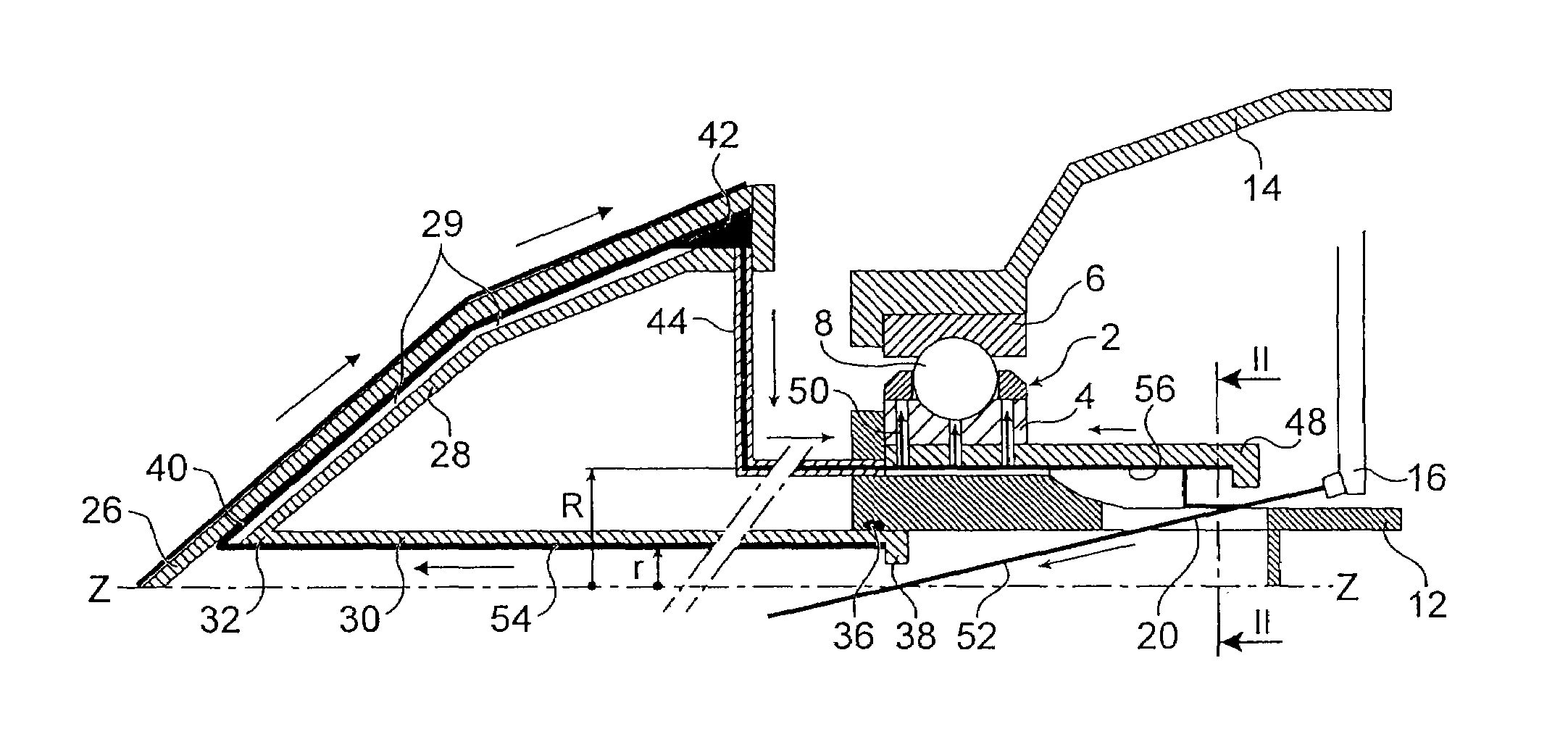
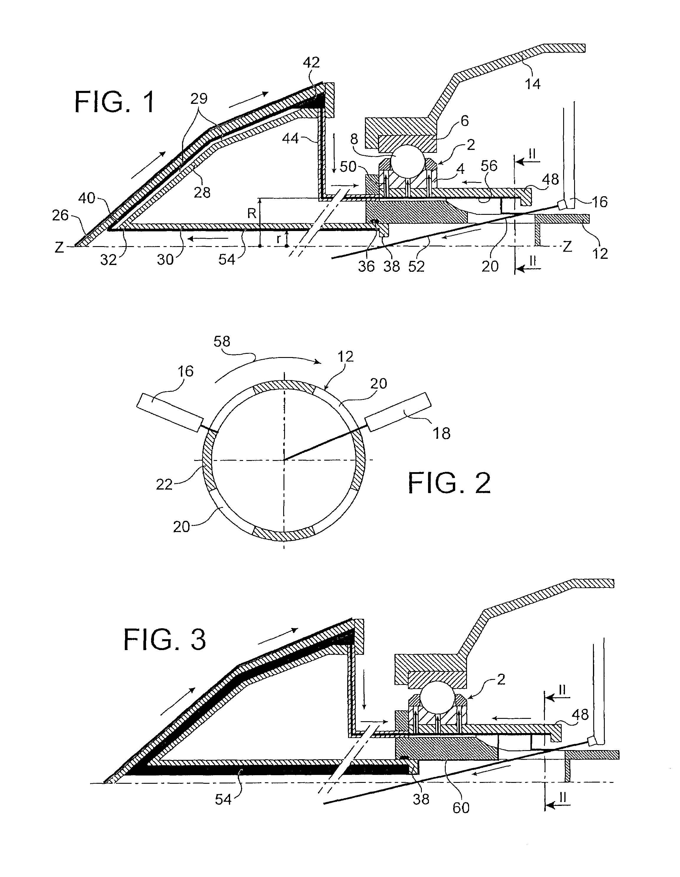
[0034]In FIG. 1, the reference 2 denotes a ball bearing. It comprises an inner race 4, an outer race 6 and balls 8. It has a rotation axis Z-Z which is at the same time an axis of symmetry. The reference 12 denotes the low-pressure shaft of the turbojet. The inner race 4 of the ball bearing 2 is mounted on the low-pressure shaft 12, while the outer race 6 of this ball bearing is mounted on a casing 14.

[0035]To feed the bearing 2 with lubricating and cooling oil, two nozzles 16 and 18 are provided (see FIG. 2). Slots 20 are formed in the low-pressure shaft 12. There is an even number of these slots, 4 in the exemplary embodiment shown. The slots 20 are separated from one another by inter-slot spaces 22. In the exemplary embodiment shown, the inter-slot spaces are the same size as the slots. However, this feature is not obligatory and, in an alternative embodiment, the slots could be smaller or larger than the inter-slot spaces.

[0036]Shown in the left-hand part of FIG. 1 is the wall 2...


PUM


Abstract

The turbojet has a bearing which supports, in rotation and in thrust, a low-pressure compressor shaft of axis Z-Z of the engine. The bearing is lubricated with oil by means of two nozzles. A feed tube is fastened to the nose cone of the engine. This tube connects the low-pressure compressor shaft to the engine nose cone. A skin lines the wall of the engine nose cone, leaving a passage for the circulation of oil. A plurality of radial oil return tubes are placed between the most eccentric part of the skin relative to the Z-Z axis and the bearing, for returning the oil to the bearing. The return of the oil into the bearing is located at a distance R from the Z-Z axis larger than the radius r of the feed tube.

Description

BACKGROUND OF THE INVENTION[0001]The invention relates to a system for deicing the nose cone of an aircraft turbojet, said turbojet having a bearing which supports, in rotation and in thrust, a hollow low-pressure compressor shaft of axis Z-Z of the engine, said bearing being lubricated with oil by means of two nozzles.[0002]In certain flight phases (climb, descent, approach), “icing” atmospheric conditions may be encountered if the ambient temperature becomes equal to or below zero Celsius and in the presence of supercooled water in clouds. These conditions may lead to unacceptable amounts of ice being deposited on the nose cone and require the installation of a system for deicing said nose cone.DESCRIPTION OF THE PRIOR ART[0003]Currently nose cones of aircraft turbojets are deiced with air. Some of the air that has been compressed, and therefore heated, in the low-pressure compressor is bled off via one or more lines. This air is injected close to the apex of the nose cone. Under ...

Claims


Application Information

Patent Timeline
Patent Type & Authority Patents(United States)
IPC IPC(8): F02C7/047F02C7/06
CPCF01D25/02F02C7/047F02C7/14F05D2260/205Y02T50/675F05D2240/50Y02T50/671F16C33/6677F16C2360/23Y02T50/60
Inventor GAUTHIER, GERARD PHILIPPEGILLE, LAURENTMORREALE, SERGE RENEPICART, JEAN-YVES
Owner SN DETUDE & DE CONSTR DE MOTEURS DAVIATION S N E C M A
Learn More