
Fuel system, especially of the common rail type, for an internal combustion engine

a fuel system and internal combustion engine technology, applied in the direction of liquid fuel feeders, machines/engines, mechanical equipment, etc., can solve the problem of prolonging the service life of the fuel system

Inactive Publication Date: 2010-01-12
ROBERT BOSCH GMBH
View PDF4 Cites 2 Cited by
  • Summary
  • Abstract
  • Description
  • Claims
  • Application Information

AI Technical Summary

Benefits of technology

The present invention is a fuel system for an internal combustion engine that prevents the pressure in the fuel system from dropping constantly below the vapor pressure after the engine and fuel system have shut off. This ensures that the engine can start quickly and reliably, even in unfavorable conditions. The fuel system includes a volume reservoir that prevents vapor formation and reduces the risk of air dissolved in the fuel. The fuel system is also simpler and more cost-effective than previous designs. The invention also provides for a demand-responsive fuel pump that can be triggered without excess pumped quantity flowing back into the fuel tank. Overall, the invention improves the starting quality and reliability of the engine while also reducing the risk of air dissolved in the fuel.

Problems solved by technology

As a result, the components in the pressure region are subjected to a lesser load, which lengthens their service life.

Method used


Image

  • Fuel system, especially of the common rail type, for an internal combustion engine
  • Fuel system, especially of the common rail type, for an internal combustion engine
  • Fuel system, especially of the common rail type, for an internal combustion engine

Examples


Embodiment Construction

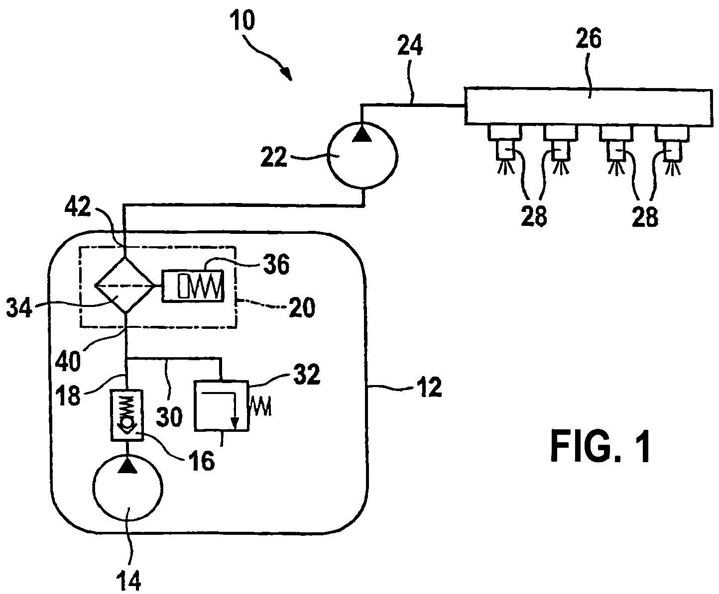
[0032]A fuel system according to the invention is identified overall in FIG. 1 by reference numeral 10. It serves to supply an internal combustion engine, which in turn drives a motor vehicle. However, the engine and vehicle are not shown in FIG. 1.

[0033]The fuel system 10 includes a fuel tank 12, in which a first fuel pump 14, also called a prefeed pump, is disposed. Via a check valve 16, it pumps fuel into a low-pressure line 18, which forms an at least intermittently closed-off pressure region. It leads out of the fuel tank 12 via a function module 20, represented here only by dot-dashed lines and described in detail hereinafter, and to a high-pressure pump 22. Pump 22 compresses the fuel to a very high pressure and pumps it onward into a high-pressure line 24, which leads to a fuel distributor 26 that is also known as a “common rail”. A plurality of injectors 28 are connected to the common rail and inject the fuel directly into combustion chambers (not shown) of the engine that ...


PUM


Abstract

A fuel system for an internal combustion engine includes at least one first fuel pump and a pressure region into which the fuel pump pumps and which communicates with an elastic volume reservoir. The elastic volume reservoir has a characteristic pressure / volume curve, which is defined by at least two points. It is proposed that a first point is defined by a first volume at a first pressure that is somewhat greater than a vapor pressure of the fuel at ambient temperature, and that a second point is defined by a second volume and a second pressure in the pressure region that corresponds to a maximum pressure; the difference between the first and second volumes corresponds at least approximately and at least to a value by which the volume of the fuel in the pressure region decreases upon cooling down from a maximum temperature to ambient temperature.

Description

REFERENCE TO FOREIGN PATENT APPLICATION[0001]This application is based on German Patent Application No. 10 2006 061 570.0 filed 27 Dec. 2006, upon which priority is claimed.BACKGROUND OF THE INVENTION[0002]1. Field of the Invention[0003]The invention relates to a fuel system, in particular of the common-rail type, for an internal combustion engine.[0004]2. Description of the Prior Art[0005]A fuel system of the type defined at the outset is known from German Patent Disclosure DE 102 36 314 A1. In the fuel system shown there, a prefeed pump pumps the fuel into a low-pressure line that forms a pressure region, to which a high-pressure pump is connected. The prefeed pump compresses the fuel to a pressure above the vapor pressure, so that the fuel can be delivered to the high-pressure pump in liquid form. The high-pressure pump compresses the fuel to the desire high pressure and pumps it to a distributor line, which is also known as a fuel collection line or common rail, to which in turn...

Claims


Application Information

Patent Timeline
Patent Type & Authority Patents(United States)
IPC IPC(8): F02M63/00F02M63/02
CPCF02D33/006F02M37/0058F02M37/20F02M37/0082F02M37/10
Inventor WOLBER, JENSSCHUMACHER, MATTHIASALBRECHT, OLIVERKOEHLER, CHRISTIANWIEDMANN, CHRISTIANNACK, LAURENT
Owner ROBERT BOSCH GMBH
Learn More