
Superlens and a method for making the same

Active Publication Date: 2010-01-05
HO SENG TIONG
View PDF7 Cites 41 Cited by
  • Summary
  • Abstract
  • Description
  • Claims
  • Application Information

AI Technical Summary

Benefits of technology

[0012]It is a general aim of the invention to provide a superlens that can control the size and the phase of an electromagnetic beam.
[0013]It is a general aim of the invention to provide a superlens that can independently control vertical and horizontal focusing.
[0014]It is an aim of the invention to increase the light coupling efficiency.
[0019]It is a further aim of the invention to provide a superlens that can reduce the spot size of a light beam used for optical storage thereby increasing the optical storage density. It is a further aim of the invention to provide a superlens that can be used in near-field optics in order to improve the transmission efficiency.

Problems solved by technology

However, the light coupling efficiency between the two optical waveguides involved in this basic process is generally low.
However, there are a few problems associated with the above-mentioned lenses.
As a semiconductor waveguide almost always has an elliptical mode profile, there is a large mode mismatch, which inherently results in low light coupling efficiency.
Thus, the coupling efficiency for coupling light between a single mode fiber and a semiconductor waveguide based device cannot be very high.
However, as the horizontal axis mode spot size of a semiconductor waveguide (such as a laser diode) is typically only about 3 to 4 μm, and the beam spot size of a single mode fiber is about 6 to 10 μm, there remains a mismatch in the horizontal mode size.
However, the vertical spot size cannot be made to match with that of a semiconductor waveguide.
The above disadvantage of vertical spot size mismatch is present in all optical-interface-refraction based lenses (including those described above).
In addition, for these lenses, especially lensed fibers, there is a large variation in the radius of curvature of the lens because each lens is made individually one at a time through processes, such as arcing or laser melting, that cannot guarantee high precision consistency.
Thus, all the above-mentioned lenses will have a relatively low coupling efficiency, and there is a low consistency in the coupling efficiency.

Method used


Image

  • Superlens and a method for making the same
  • Superlens and a method for making the same
  • Superlens and a method for making the same

Examples


Embodiment Construction

[0038]The present invention provides an apparatus that can control the size and the phase of an electromagnetic beam, and can independently focus it in the horizontal and vertical directions. The present invention also describes a method to create such an apparatus. To improve the understanding of the present invention, fundamental concepts related to the invention are herein described.

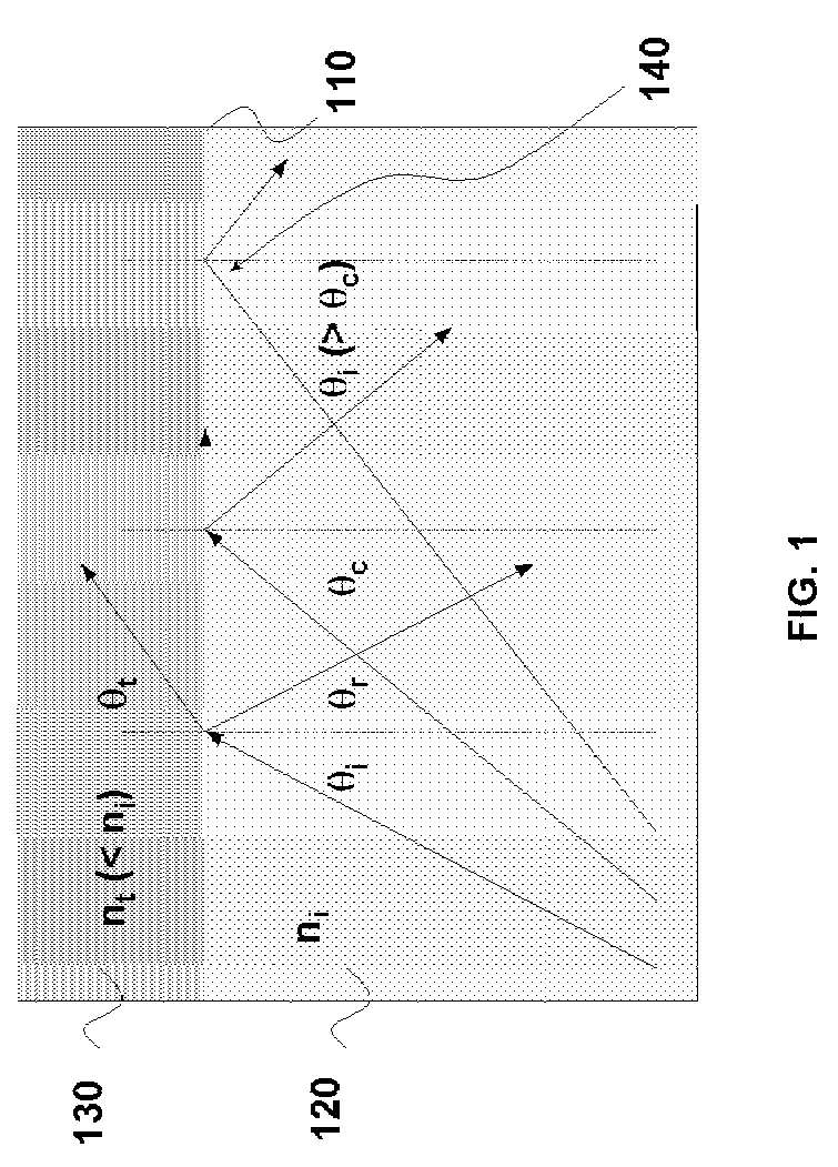
[0039]Fundamental Concepts: An electromagnetic wave is characterized by a wavelength and a frequency with which it oscillates. Further, the electromagnetic wave travels at a speed that depends on the medium through which it is traveling. The speed of the electromagnetic wave decreases as it travels from vacuum to a medium. The ratio of the speed of electromagnetic wave in vacuum (c) and the speed in the medium (v) is a property of the medium and is referred to as the refractive index (n) of the medium.

[0040]When the electromagnetic wave travels through a medium, the frequency of the electromagnetic wa...


PUM


Abstract

A superlens for controlling the size and the phase of an electromagnetic beam that passes through it, and a method for independently controlling the horizontal and vertical focusing of the electromagnetic beam using the superlens is provided. The superlens comprises a vertically GRIN multi-layer structure with one or more horizontally curved sidewalls. The vertical focusing is controlled by varying the longitudinal thickness of the multi-layer structure. The horizontal focusing is controlled by varying the profile and the radius of curvature of the horizontally curved sidewalls. Varying the thickness and radius of curvature is done by etching. Also provided is a method for making the superlens.

Description

[0001]The present patent document claims the benefit of the filing date under 35 U.S.C. §119(e) of U.S. Provisional Patent Application Ser. No. 60 / 454,806, filed on Mar. 14, 2003.CROSS REFERENCE TO RELATED APPLICATIONS[0002]This application is related to U.S. patent application Ser. No. 10 / 083,674, “Integrated Planar Composite Coupling Structures for Bi-directional Light Beam Transformation Between a Small Mode Size Waveguide and a Large Mode Size Waveguide,” filed Oct. 22, 2001, in the names of Yan Zhou and Seng-Tiong Ho, the disclosure of which is incorporated herein by reference. This application is also related to a pending U.S. Patent Application filed with U.S. patent application Ser. No. 10 / 651,372, entitled “Optical Beam Transformer Module for Light Coupling between a Fiber Array and a Photonic Chip and the Method of Making the Same,” filed in the names of Yan Zhou, Shide Cheng and Seng-Tiong Ho, the disclosure of which is incorporated herein by reference. This application i...

Claims


Application Information

Patent Timeline
IPC IPC(8): G02B6/10G02B6/32
CPCG02B3/0087G02B6/124G02B6/14
Inventor ZHOU, YANHO, SENG-TIONG
Owner HO SENG TIONG
Learn More