Large pallet machine for forming molded products

a pallet machine and product technology, applied in the field of concrete product making machinery, can solve the problems of increased wear on these parts, shoes that impact the interior of the mold cavity, and time-consuming to change molds, and achieve the effect of reducing material scalping, easy installation and removal

Active Publication Date: 2009-12-22
KORONBIA MACH
View PDF22 Cites 11 Cited by
  • Summary
  • Abstract
  • Description
  • Claims
  • Application Information

AI Technical Summary

Benefits of technology

[0012]The apparatus includes a means for vibrating the pallet table directly along with a novel means for maintaining the vibration in a generally vertical direction to reduce impacts of the mold shoes with the inside of the mold cavities. The vibration direction control means includes pairs of leaf spring-like parallel bars, coupling the die supports to the main frame, and a torsion bar, coupling the die supports to each other. Air springs, mounted within the die supports and acting as shock absorbers for the vibrating mold box, are inflated as needed to control the stiffness of the shock-absorbing means.
[0014]An additional novel feature is the use of an air knife to produce an air stream between the feed drawer bottom plate and the edge of the mold to prevent material from falling into the gap between the two elements. Air is forced under pressure through a slot having an approximate length of the interface between the mold box and the feed drawer. This air flow creates an upward airstream that results in closing the gap, greatly reducing material from falling through the opening between the mold and the feed drawer bottom plate.
[0016]The vibration mechanism is coupled to a series of vertical bars on which the pallet sits. Vibratory forces, imparted from the rotating counterweights mounted to the underside of the pallet table transfer the vibratory forces through the pallet and into the mold box by impacting upward into the pallet and the mold box frame. The mold box then vibrates in a generally vertical direction by action of the leaf spring parallel bars and torsion bar as described above. This is a reversal of the prior methods for shaking the mold box to increase material density and remove voids in the concrete where the die supports on which the mold rests are vibrated rather than the pallet table on which the bottom of the pallet rests.
[0018]Another novel feature of the present apparatus is the use of a vibrating strike-off plate that is dragged over the top of the now-filled mold to wipe away excess concrete. A set of vibrators, one at each end of the strike-off plate are initiated to run during the return cycle of the feed drawer. This vibrating motion of the strike-off plate acts like a screed and assists in minimize scalping of material left on top of the mold.
[0019]Yet another novel feature is the use of a spring activated seal formed between the moveable feed drawer and the stationary plate on which it sits. A set of seal bars located on the sides and at the rear of the feed drawer act as seal between the feed box and the feed drawer bottom plate to contain the concrete material within the feed box. These replaceable bars are mounted in a manner that allows a series of springs to apply pressure pushing the seal bar against the feed drawer bottom plate. This spring movement allows the bar to remain against the bottom even as wear occurs.
[0020]Rotary agitators are included within the feed drawer and affixed at their ends to drive mechanisms on the sides of the feed drawers. The agitators include rods or paddles that mix the concrete material to keep the material from solidifying and to also drive the material in the desired direction (e.g., toward the mold box when the feed drawer moves over the top of the mold cavities). Each end of the agitator has a square cross-section and is received in complementary slots designed into the drive mechanism. A sleeve is then fitted over each end and positioned over the slot in the drive mechanism to maintain the agitator within the feed box. The drive mechanism is driven by an electric motor located outside the feed box. The agitators may thus easily be installed and removed. The agitator shafts are covered with a urethane sleeve, also a novel design, that helps prevent concrete from building up on the agitators during use.

Problems solved by technology

Several drawbacks have been identified with these prior concrete products forming machines.
First, it has traditionally been quite time consuming to change mold and corresponding shoe assemblies so that new product configurations can be produced in the machine.
Second, prior art vibration systems are known to impart slightly horizontal vibrational forces which cause the shoes to impact against the interior of the mold cavities when inserted.
This results in increased wear on these parts with early and costly replacement necessary.
Third, the process of moving of concrete material from the feed box to the mold cavities is a fairly messy procedure.
Again, efficiency and product quality is reduced due to the requirement of frequent clean-ups.
Finally, prior art concrete products forming machines have traditionally been produced using hydraulic power systems which are noisy, energy inefficient, requires high maintenance, are messy, and are unwieldy with hoses and tubes routed through and around the machine.

Method used


Image

  • Large pallet machine for forming molded products
  • Large pallet machine for forming molded products
  • Large pallet machine for forming molded products

Examples


Embodiment Construction

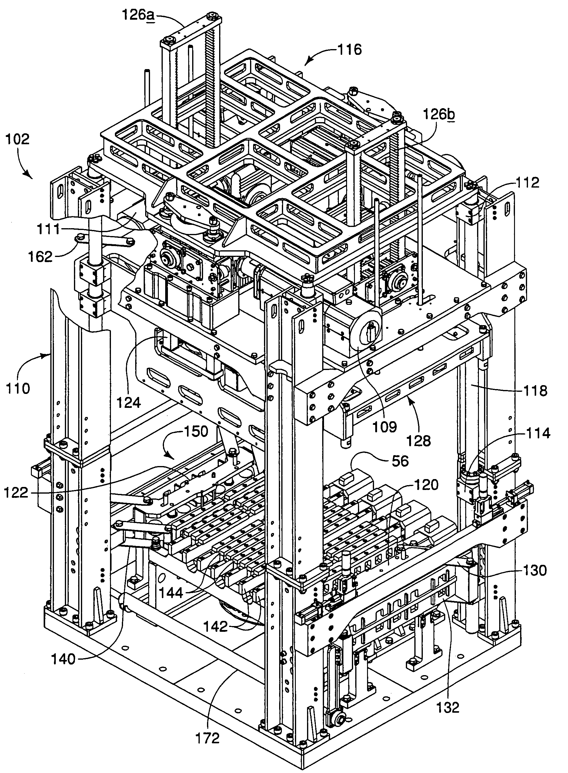
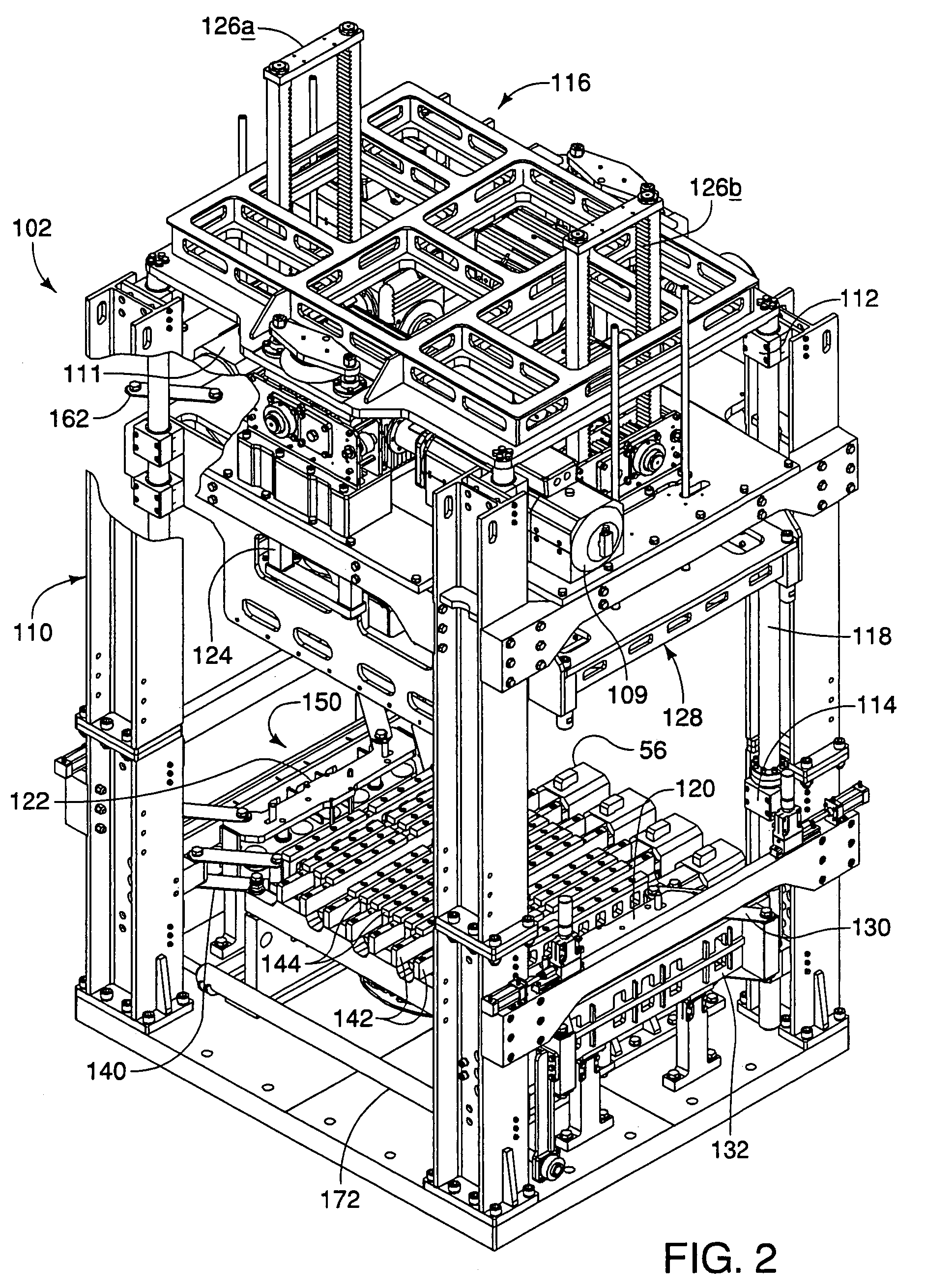
[0038]The novel features of the present invention include air spring die supports; parallel bar alignment of the die support, pallet table, and mold head plate; automatic mold and mold head installation; operation using electric drive motors utilizing servo motors for precision positioning of components and for installing and removing the retaining nuts; torsion bar interface connection of die supports; key slots for mold head installation; reduced noise resulting from the lack of a hydraulic pump; smooth operation of the electric motors; oil mist lubrication for the vibration system; positive air flow for sealing between the mold and the feed drawer; feed belt drive; rotary agitators; vibrating strike-off plate; agitators designed for easy removal and replacement; spring adjustable feed drawer side seals; and spring controlled rear seal.

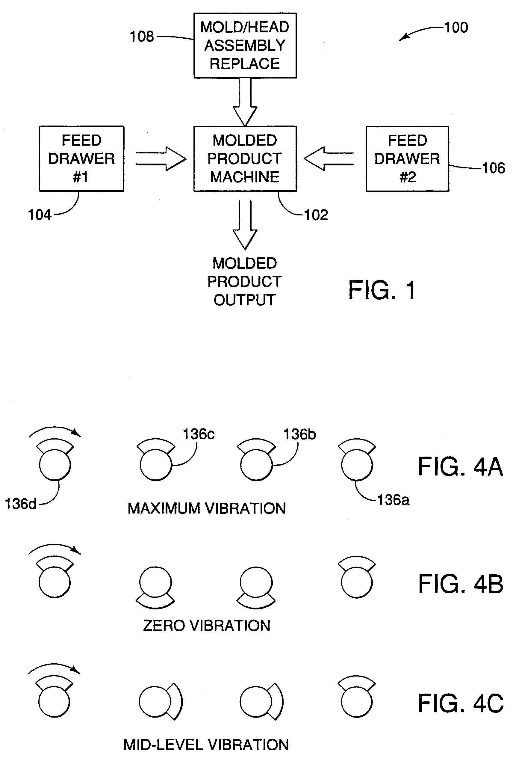
[0039]FIG. 1 shows generalized components of a large pallet machine at 100 for forming molded products, such as pavers, srw's and block formed from...


PUM

PropertyMeasurementUnit
heightaaaaaaaaaa
pressureaaaaaaaaaa
phaseaaaaaaaaaa

Abstract

A concrete products forming machine including a main frame, feed drawers, die supports and mold and head assemblies. The feed drawer is moved into position over the mold using an electric belt drive system and includes a vibrating strike off plate to improve surface quality of the molded product, zoned agitators to control movement and placement of concrete, a spring loaded seal system between the walls and floor of the feed box, and quick-release agitator design with urethane sleeves to effect easy and clean removal, replacement and cleaning of the agitators. The concrete products forming machine includes torque tube and leaf spring supports to effect substantially vertical vibrational movement of the mold with air inflatable springs for controlled force between the mold bottom and the pallet. The pallet itself is vibrated from below using phased, counter rotating shafts coupled to the pallet table on which the pallet rests. Vibration induced into the pallet by the vibrating pallet table is transferred to the mold resulting in material compaction. After the molding process, the mold is lifted in a stripping process to remove the molded product for curing or drying.

Description

CROSS-REFERENCES TO RELATED APPLICATIONS[0001]This application claims the benefit from U.S. Provisional Patent Application No. 60 / 648,018 filed Jan. 27, 2005 whose contents are incorporated herein for all purposes.BACKGROUND OF THE INVENTION[0002]1. Field of the Invention[0003]This invention relates generally to concrete product making machinery and more particularly to a method and apparatus for high speed manufacturing of a wide variety of high quality products.[0004]2. Description of the Prior Art[0005]Prior art machines for forming concrete products within a mold box and include a product forming section comprising a stationary frame, an upper compression beam and a lower stripper beam. The mold box includes a head assembly that is mounted on the compression beam, and a mold assembly that is mounted on the frame and receives concrete material from a feed drawer. An example of such a system is shown in U.S. Pat. No. 5,807,591 which describes an improved concrete products forming ...

Claims


Application Information

Patent Timeline
Patent Type & Authority Patents(United States)
IPC IPC(8): B28B1/087
CPCB28B1/081B28B1/0873B28B3/022B28B17/009B28B13/0235B28B15/005B28B13/023
Inventor HIGH, DOUGLAS VERNONGILDERSLEEVE, STACY L.WAHLSTROM, DANIEL RICHARDJOHNSTON, LLEWELLYN LEEBREWER, KEITH DONALD
Owner KORONBIA MACH
Why Eureka
Try Eureka