Energy recovery system

a technology of energy recovery and energy storage, which is applied in the direction of machines/engines, lighting and heating apparatus, machine operation mode, etc., can solve the problem that the normal operation of the power source and other working devices cannot increase the temperature of the power source and other working devices (the temperature of the coolant) above a certain level, and the temperature difference between the coolant and the outside air cannot be sufficient for generating electricity, so as to improve energy efficiency and reliably generate electricity

Inactive Publication Date: 2009-12-08
TOYOTA JIDOSHA KK
View PDF18 Cites 29 Cited by
  • Summary
  • Abstract
  • Description
  • Claims
  • Application Information

AI Technical Summary

Benefits of technology

[0009]Accordingly, it is an objective of the present invention to provide an energy recovery system that improves energy efficiency, while reliably generating electricity with a thermoelectric converter.

Problems solved by technology

When the power source and other working devices of a vehicle are operating, heat from the power source and other working devices escapes as waste heat.
However, in a vehicle using an energy recovery system according to the above publication, normal operation of the power source and other working devices cannot increase the temperature of the power source and other working devices (the temperature of the coolant) above a certain level.
Therefore, the temperature difference between the coolant and the outside air can be insufficient for generating electricity with the thermoelectric converter.
However, the control for increasing the temperature of the power source and other working devices can adversely affect the power source and other working devices.
However, although the temperature of the coolant is relatively stable, the temperature of the exhaust greatly varies depending on the operating state of the engine, for example, in a range from 100° C. to 800° C. Such great temperature changes can damage the thermoelectric converter.
However, if a great amount of energy is consumed to drive the refrigeration apparatus so that the low temperature refrigerant is maintained to be cold, a possible improvement of the energy efficiency, which would be brought about by the energy recovery system, is hindered.
Such problems occur not only in a case where the energy recovery system is used in a vehicle such as an automobile, but also in a case where the energy recovery system is applied to various apparatuses other than vehicles.

Method used


Image

  • Energy recovery system
  • Energy recovery system
  • Energy recovery system

Examples


Embodiment Construction

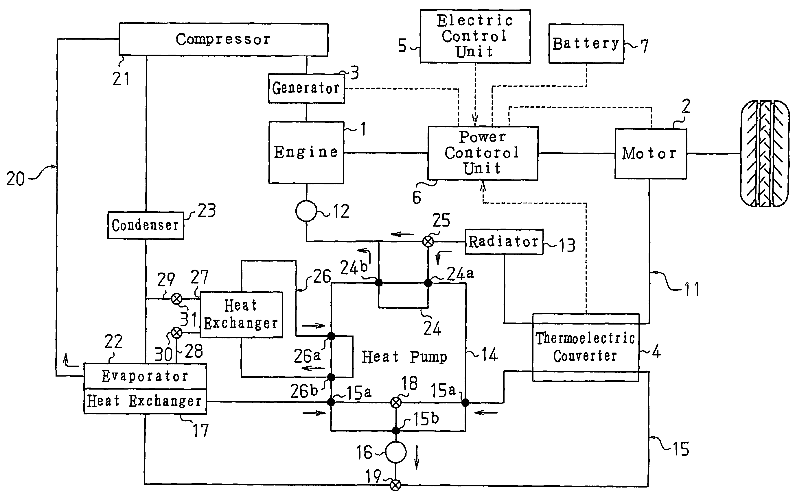
[0014]An energy recovery system according to one embodiment of the present invention will now be described with reference to FIGS. 1 to 3. The energy recovery system is used in a hybrid automobile.

[0015]As shown in FIG. 1, the hybrid automobile has an engine 1 and a motor 2 as drive sources. The automobile also has a generator 3 and a thermoelectric converter 4 for charging a battery 7. The generator 3 is driven by the engine 1 to generate electricity. The thermoelectric converter 4 uses waste heat from the vehicle to generate electricity. Charging of the battery 7 with electricity generated by the thermoelectric converter 4 allows waste heat from the automobile to be recovered as electrical energy. The output of the generator 3 and the thermoelectric converter 4 and the operation of the motor 2 are controlled by a power control unit 6, which is controlled by an electric control unit 5.

[0016]The hybrid automobile further has an engine coolant circuit 11, in which engine coolant (hig...


PUM


Abstract

An energy recovery system for hybrid automobile. The energy recovery system generates electricity by utilizing the temperature difference between a high temperature thermal medium and a low temperature thermal medium. As the high temperature thermal medium, engine coolant for cooling an engine is used. As the low temperature thermal medium, pump refrigerant for cooling by a heat pump is used. The heat pump maintains the pump refrigerant at a low temperature by using heat from the engine coolant. Therefore, while electricity is reliably generated at a thermoelectric converter, energy is efficiently used for cooling the pump refrigerant.

Description

FIELD OF THE INVENTION[0001]The present invention relates to an energy recovery system.BACKGROUND OF THE INVENTION[0002]Energy recovery systems have been proposed for recovering surplus energy produced during operation of various kinds of working devices to improve the energy efficiency of the working devices. Such an energy recovery system converts heat generated during operation of the working devices into electrical energy. A typical energy recovery system has a thermoelectric converter that generates electricity by utilizing a temperature difference between a high temperature thermal medium (high temperature medium) and a low temperature thermal medium (low temperature medium). As a high temperature medium, a thermal medium that receives heat during operation of the working devices is used, and as a low temperature medium, a thermal medium the temperature of which is lower than the high temperature medium is used. The thermoelectric converter uses waste heat from the working dev...

Claims


Application Information

Patent Timeline
Patent Type & Authority Patents(United States)
IPC IPC(8): H01L35/30B60H1/00F25B15/02F25B27/02H01L35/00
CPCB60H1/004B60H1/143H01L35/30F25B27/02H01L35/00B60H2001/2275F25B15/02Y02A30/274Y02A40/963H10N10/00H10N10/13
Inventor INAOKA, HIROYA
Owner TOYOTA JIDOSHA KK
Why Eureka
Try Eureka