Eureka AIR delivers breakthrough ideas for toughest innovation challenges, trusted by R&D personnel around the world.

Collapsible and expandable instrument for insertion in a dorsal vertebra

a dorsal vertebra and expandable technology, applied in the field of instruments, can solve the problems of reducing the recovery time of patients, affecting the recovery of patients, and few suitable techniques for restoring the height of damaged vertebrae, and achieve the effect of short recovery time for patients

Inactive Publication Date: 2009-12-01
MANDACO 569 LTD
View PDF21 Cites 124 Cited by
  • Summary
  • Abstract
  • Description
  • Claims
  • Application Information

AI Technical Summary

Benefits of technology

[0008]An advantageous aspect of the invention is the fact that the instrument has been designed such that the surgeon can perform the operation with minimal invasive surgery. In order for the technique to become generally accepted, minor and rapid surgery and a short recovery time for the patient are essential.
[0010]Another advantageous aspect is the fact that the restoration of the shape and the dimensions of the vertebral body can easily be checked by the surgeon, with the surgeon being able to withdraw the instrument if he is not absolutely certain that the instrument is correctly positioned.
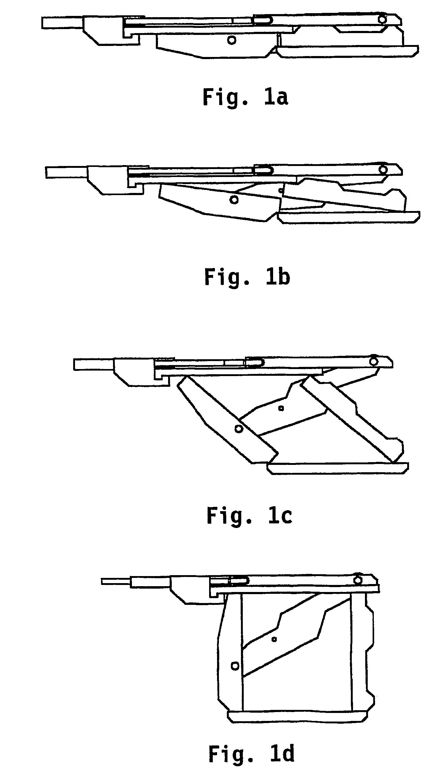
[0012]The instrument according to the invention may have a small width dimension and, in the collapsed position, also a small height dimension. In this position, the instrument can be inserted into the vertebral cavity via two small incisions in the patient's tissue and two small opening is in the vertebral wall. All this with a minimum degree of discomfort to the patient and under circumstances which ensure a quick recovery of the area in question. After the instrument has been inserted, the two contact elements are moved apart until they press against the upper and lower end faces of the vertebra in question with a specific, predetermined force in their end position, thus restoring the vertebra to its original dimension. In this position, the contact elements are fixated relative to each other. Now the surgeon can introduce a material, such as minerals or bone cement, into the space thus formed. The load on the vertebra is initially taken up nearly entirely by the instrument, so that bone growth can take place without the restored position of the vertebra being affected. Once a sufficient amount of bone of sufficient strength has been formed, said newly formed the bone will gradually take over the load on the instrument, all this analogously to the aforementioned cage techniques. Since the instrument has directly returned the vertebra to its original shape and fixated it therein, the pain which the patient experiences will be much less from the outset already.

Problems solved by technology

If the quality of the bone tissue inside a vertebra deteriorates due to illness, such as osteoporosis, trauma and the like, the surrounding bone tissue may be subjected to an ever increasing pressure, which may lead to said tissue collapsing as well and the vertebra being compressed, with all the unpleasant consequences thereof.
Although various methods are known for restoring the height of an intervertebral disc; see International patent WO 01 / 03616, for example, only few suitable techniques are known for restoring the height of a damaged vertebra.
It is known, for example, to replace a damaged vertebra in its entirety by a prosthesis, but this is a very radical operation which is only performed in exceptional cases.
One drawback of this method is the fact that the inserted material is subjected to a pressure upon releasing of the balloon pressure, as a result of which said material may leak out, so that it will no longer perform its function to its full extent.
Furthermore, the quality of the fusion between the inserted material and the surrounding bone tissue is not fully satisfactory, resulting in a less than optimum long-term strength and quality of the treated vertebra.

Method used


Image

  • Collapsible and expandable instrument for insertion in a dorsal vertebra
  • Collapsible and expandable instrument for insertion in a dorsal vertebra
  • Collapsible and expandable instrument for insertion in a dorsal vertebra

Examples


Embodiment Construction

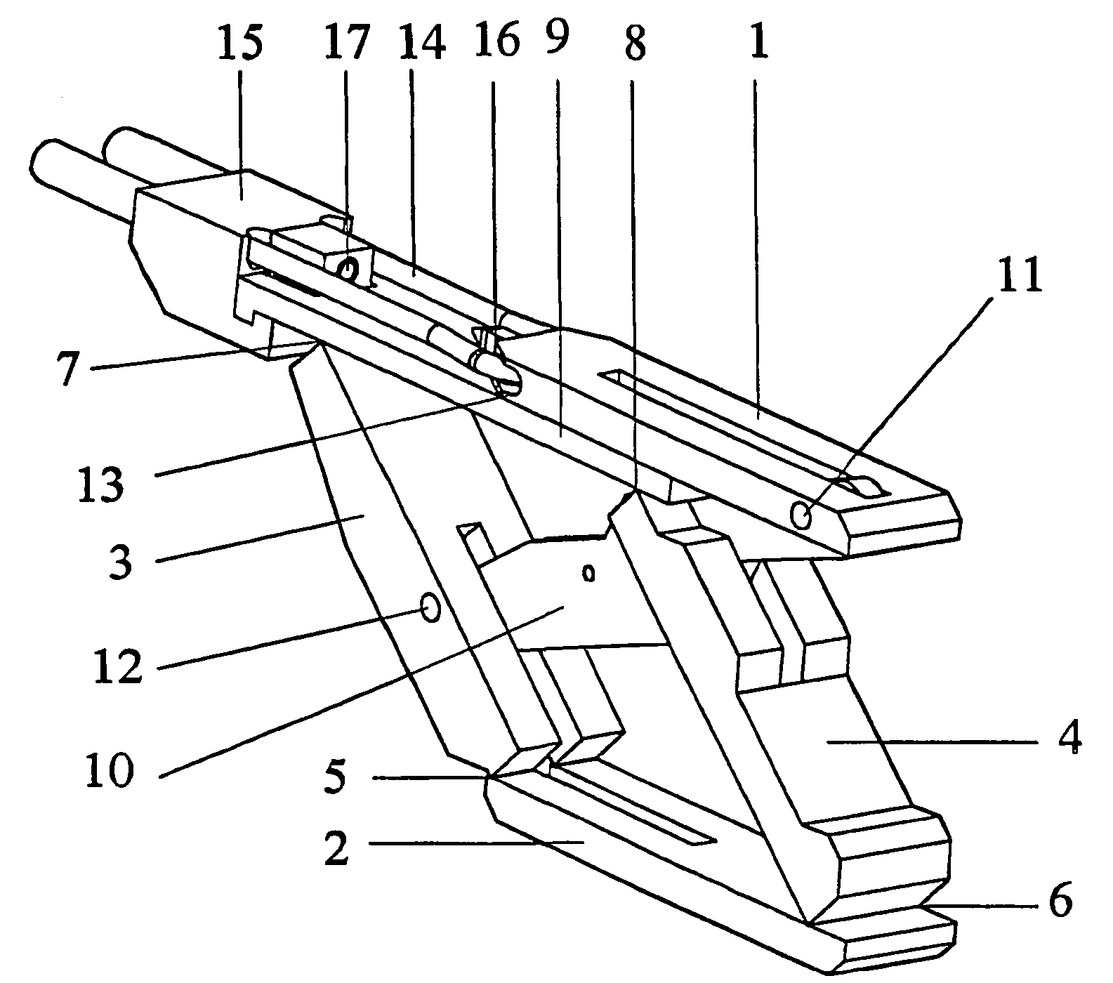
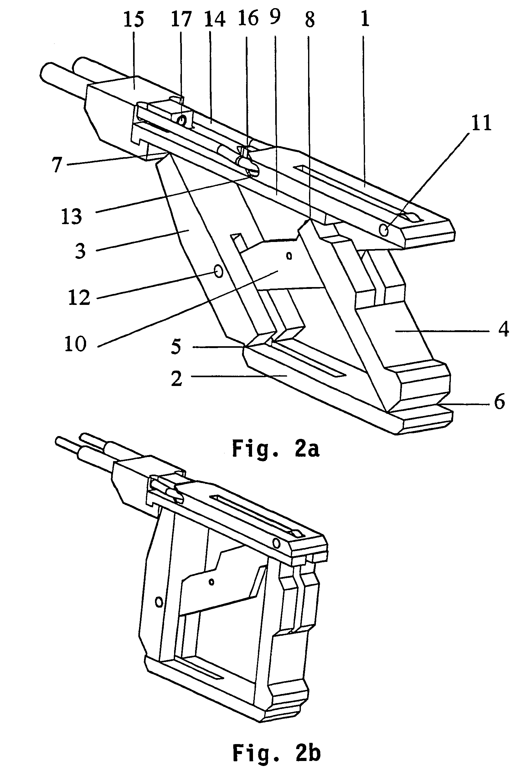
[0030]In FIG. 2a, numeral 1 indicates a first, upper, elongated contact element. Numeral 2 indicates a second, lower, likewise elongated contact element. Two parallel arms 3 and 4 are pivotally connected to the lower contact element 2 by means of hinges 5 and 6, respectively. At their other ends, the arms 3, 4 are pivotally connected, at points 7, 8, respectively, to a beam-shaped element 9 which is slidably connected to the bottom side of the upper contact element 1. In its end position as shown in FIG. 2b, a lever 10 is connected to the upper elongated contact element 1 with one end by means of a pivot 11, approximately at the level of parallel arm 4. The lever 10 is connected to the parallel arm 3, approximately at the centre thereof, with its other end by means of a pivot 12.

[0031]The upper contact element is provided with a cavity 13, through which a cord 14 is passed, the free ends of which are fixed in a detachable tensioning device 15 connected to the beam-shaped element 9, ...


PUM


Abstract

An instrument in particular suitable for being inserted into the cavity within a vertebra, which instrument features a collapsed position and an expanded position, in which collapsed position the instrument can be inserted into the cavity through an opening in the vertebral wall. The instrument includes a first upper elongated contact element and a second lower elongated contact element, and member for moving said elements apart in a direction substantially transversely to their contact surfaces to a particular end position, in which the elements are locked in position relative to each other.

Description

FIELD OF THE INVENTION[0001]The present invention relates to an instrument in particular suitable for being inserted into the cavity within a vertebra, which instrument features a collapsed position and an expanded position, in which collapsed position the instrument can be inserted into the aforesaid cavity through an opening in the vertebral wall.DESCRIPTION OF THE RELATED ART[0002]If the quality of the bone tissue inside a vertebra deteriorates due to illness, such as osteoporosis, trauma and the like, the surrounding bone tissue may be subjected to an ever increasing pressure, which may lead to said tissue collapsing as well and the vertebra being compressed, with all the unpleasant consequences thereof.[0003]Although various methods are known for restoring the height of an intervertebral disc; see International patent WO 01 / 03616, for example, only few suitable techniques are known for restoring the height of a damaged vertebra.[0004]It is known, for example, to replace a damag...

Claims


Application Information

Patent Timeline
Patent Type & Authority Patents(United States)
IPC IPC(8): A61F2/44A61B17/56A61B17/00A61B17/02A61B17/70A61B17/88A61F2/00A61F2/30A61F2/46
CPCA61F2/44A61F2/4611A61B17/8852A61B17/70A61F2230/0021A61B17/8858A61B2017/00261A61B2017/00539A61B2017/00544A61B2017/00557A61B2017/0256A61F2002/30153A61F2002/30154A61F2002/30476A61F2002/30492A61F2002/30579A61F2002/30624A61F2002/30626A61F2002/4475A61F2002/448A61F2002/4627A61F2220/0025A61F2230/0019A61F2002/30593A61B17/56A61F2/28A61B17/58
Inventor VELDHUIZENGEENEN, KAMIEL REINER ZALE
Owner MANDACO 569 LTD
Why Eureka
Eureka Blog
Learn More