
Recovery of network element configuration

a network element and configuration technology, applied in the field of telecommunications, can solve the problems of failure of network elements, corruption of configuration information of network elements,

Inactive Publication Date: 2007-01-25
ALCATEL LUCENT SAS
View PDF10 Cites 22 Cited by
  • Summary
  • Abstract
  • Description
  • Claims
  • Application Information

AI Technical Summary

Benefits of technology

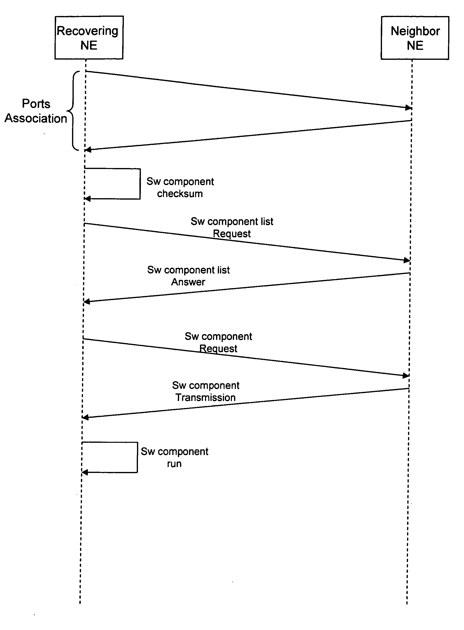
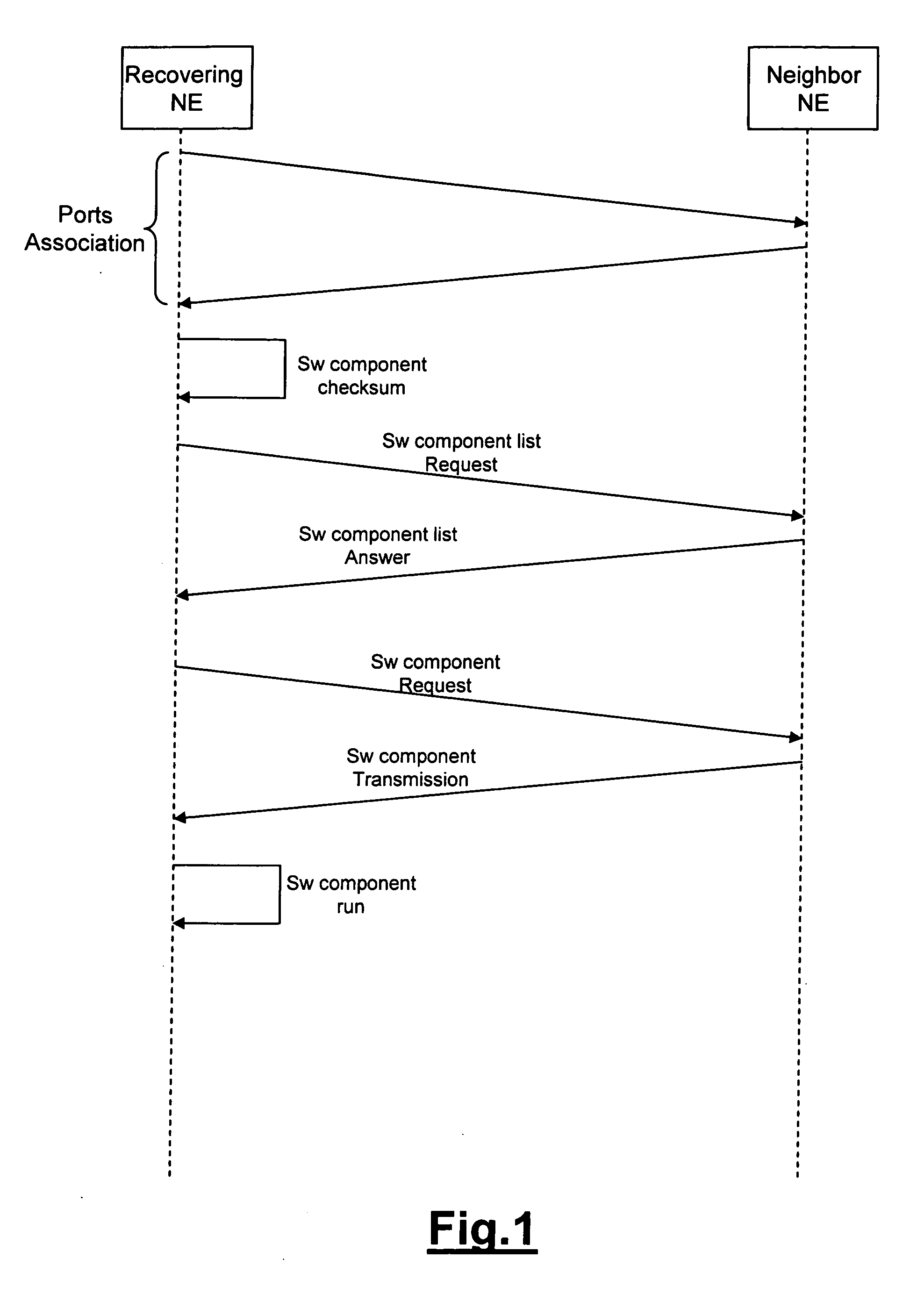
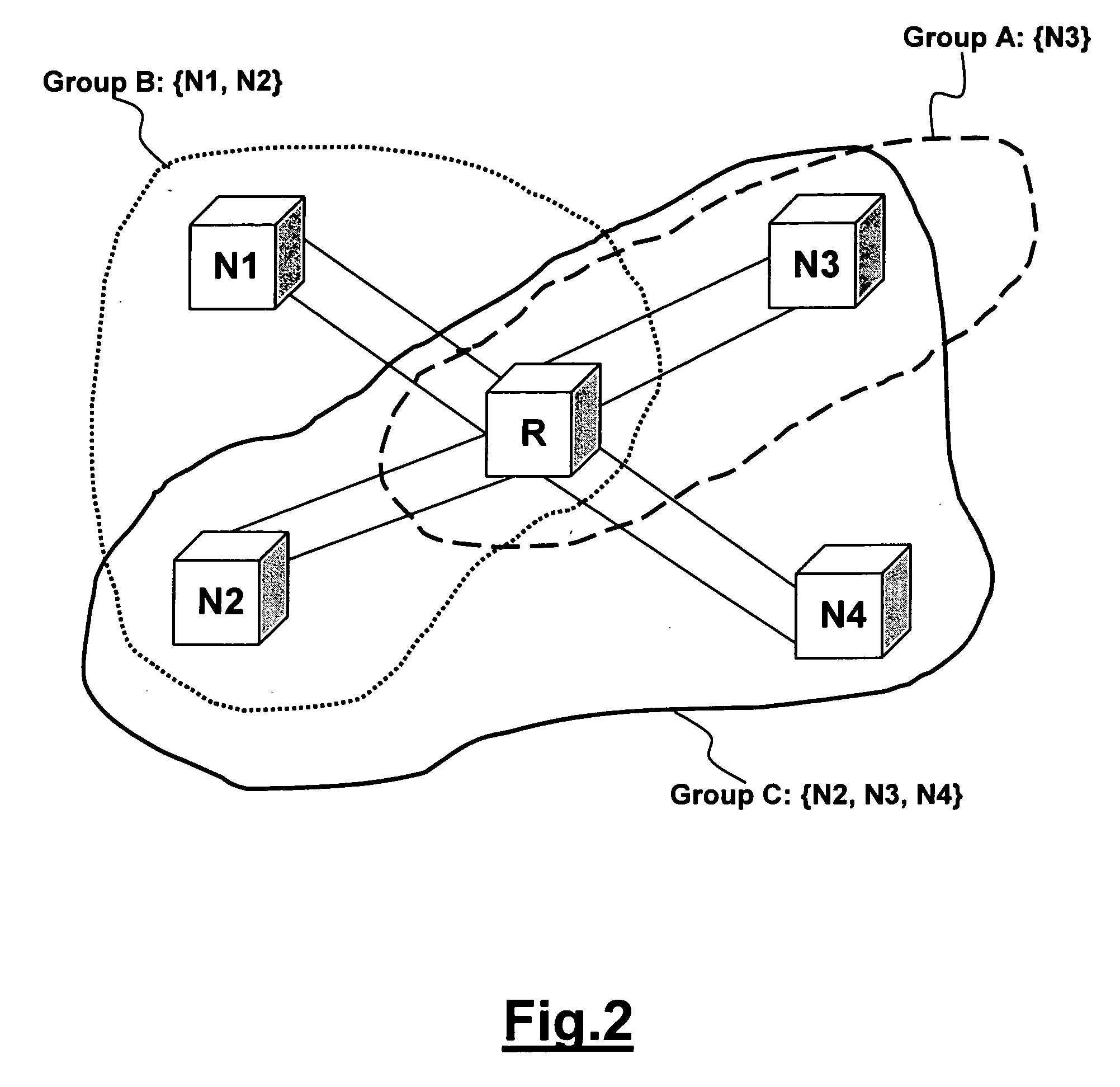
The present invention provides a method for recovering corrupted configuration information of a network element without using a central network management station. The method involves sharing the configuration information among a group of neighbor network elements and transmitting correlated configuration information to the recovering network element to recover its configuration. The invention has the advantages of requiring a small recovery time, allowing recovery of multiple corrupted configuration information at the same time, and being applicable even in cases of failure of the central network management station or intermediate network elements.

Problems solved by technology

In a telecommunication network corruption of the configuration information of a network element can occur.
In fact the configuration information is stored locally to the network element into a memory (for example a non-volatile memory like an hard disk or a volatile memory like a RAM=Random Access, Memory) and corruption can occur for example for the following reasons: the data read from the memory can include errors; the memory can be affected by file system failures; a failure of a board mounting the memory or a failure of the network element can occur, for example for power supply problems.
Corruption of the configuration information can also occur in case of an uncorrect provisioning of the network element configuration, for example during setup of the network; this occurs, for example, if the configuration of a network element doesn't fit the configuration of other network elements directly or indirectly connected.
In both cases the consequence is corruption (errors or lost) of configuration information stored in the network element, like for example: software programs files; a database of configured cross-connections between input and output ports of the network element; a database of the configured connections crossing the network element; a database of performance monitoring functions for the configured connections crossing the network element.
The corruption can be traffic affecting and thus it is required an automatic recovery mechanism with a small recovery time, that is a small time required for restoring the correct configuration information after detection of the corruption.
Since the bandwidth available between the manager and the controlled network elements is limited, this solution has the following disadvantages: it requires a too long recovery time in case of transmission of a big configuration information file; in case of multiple corruptions at the same time, few simultaneous transmissions are possible.
Moreover, the corrupted network element could be not reachable by the management station: this can occur if there are failed intermediate network elements before the corrupted network element and the management station can reach the corrupted network element only crossing the failed network elements.
This solution is timely efficient and can also allow to recover from multiple corruptions at the same time, but it is too expensive because it requires duplication of hardware resources.
Moreover, it has the disadvantage that in some cases the backup configuration information must be updated, because the configuration information can change.
Therefore it is required to update periodically the backup configuration information by transmitting updated backup configuration information from the central network management station to each controlled network element and this increases the management traffic between the central network management station and the controlled network elements (wherein the bandwidth is limited).

Method used


Image

  • Recovery of network element configuration
  • Recovery of network element configuration
  • Recovery of network element configuration

Examples


Embodiment Construction

[0031] The recovering network element can communicate with neighbor network elements and it can be directly connected or indirectly through intermediate network elements. This is achieved, for example, by the Control Plane Elements of the new network architectures, based on the Automatically Switched Optical Network (ASON) defined in ITU-T G.8080 / Y.1304 (11 / 2001), wherein the control plane elements (CPEs) are interconnected each other and communicate according to a signalling protocol. Each CPE controls one or more network elements, also defined Transport Plane Elements (TPE), for configuration of the connections starting from the controlled network element (also defined source network element), in order to provide a fast detection of a failure, a fast and efficient configuration of new connections within the Transport Plane, modify the connections previously set up and perform a faster restoration function providing backup connections for protecting connections affected by a failur...


PUM


Abstract

A method is described for recovering corrupted configuration information stored in a recovering network element of a telecommunication network. The network includes neighbor network elements storing configuration information correlated to the configuration information stored in the recovering network element. The method includes the transmission to the recovering network element of correlated configuration information stored in the neighbor network elements. The method further includes selection of the neighbor network elements from possible network elements taking into account bandwidth of channel available for the transmission, estimation of time required for the transmission, estimation of round trip delay, number of intermediate network elements, reliability of the possible network elements.

Description

FIELD OF THE INVENTION [0001] The present invention relates to the telecommunication field and more in particular to a method for increasing the availability of a telecommunication network. Still more in particular, the invention concerns a method for the recovery of corrupted configuration information of network elements. [0002] This application is based on and claims the benefit of European Patent Application No 05291596.4 filed on Jul. 22, 2005, which is incoporated by reference herein. BACKGROUND OF THE INVENTION [0003] In a telecommunication network corruption of the configuration information of a network element can occur. In fact the configuration information is stored locally to the network element into a memory (for example a non-volatile memory like an hard disk or a volatile memory like a RAM=Random Access, Memory) and corruption can occur for example for the following reasons: [0004] the data read from the memory can include errors; [0005] the memory can be affected by f...

Claims


Application Information

Patent Timeline
Patent Type & Authority Applications(United States)
IPC IPC(8): H04L27/00
CPCH04L41/0206H04L41/0663H04L41/0869H04L41/0859H04L41/0863H04L41/0836H04L41/052
Inventor DONADIO, PASQUALEPAPARELLA, ANDREARIGLIETTI, ROBERTO
Owner ALCATEL LUCENT SAS
Learn More