Liquid jetting device
a technology of liquid ejecting device and liquid ejector, which is applied in the direction of printing, etc., can solve the problems of large space occupation of total ink supply tubes, large number of assembling steps, and ineffective cost reduction, and achieves the effect of reducing labor intensity, reducing labor intensity, and simplifying the construction of sub tanks
- Summary
- Abstract
- Description
- Claims
- Application Information
AI Technical Summary
Benefits of technology
Problems solved by technology
Method used
Image
Examples
first embodiment
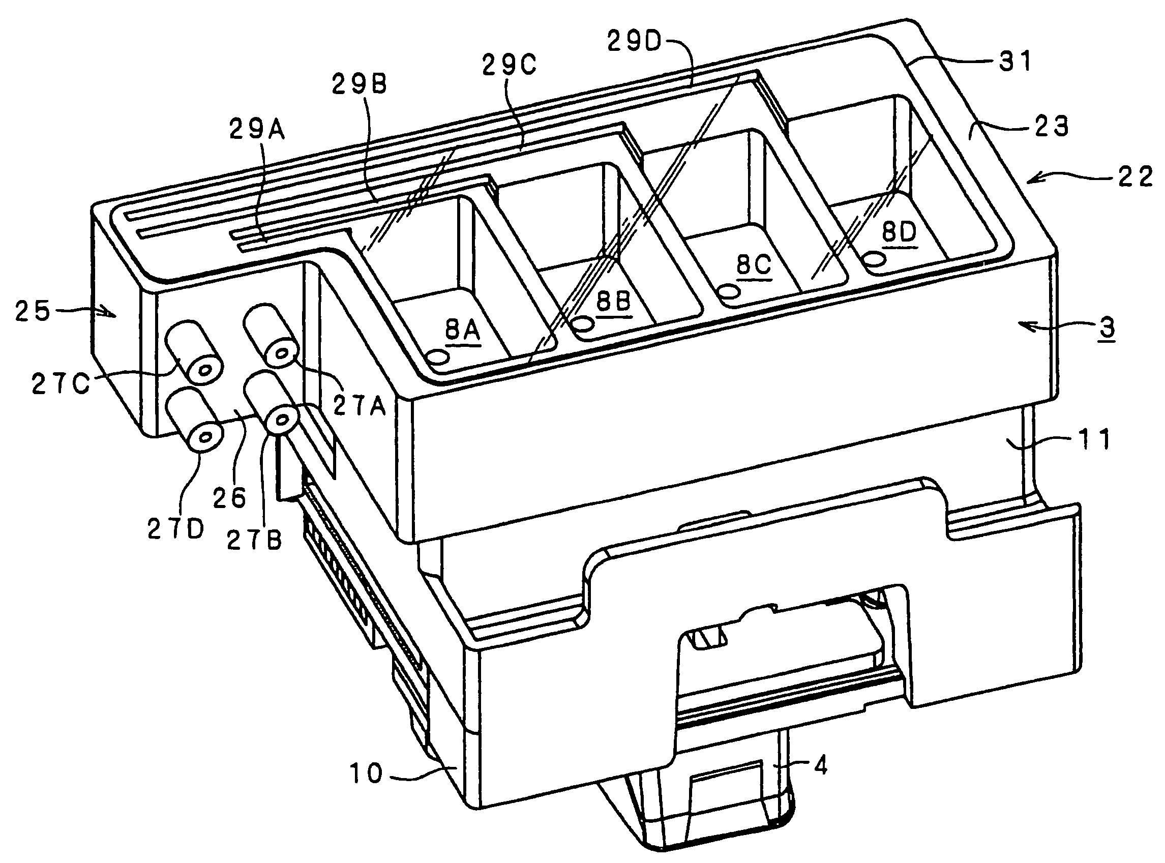
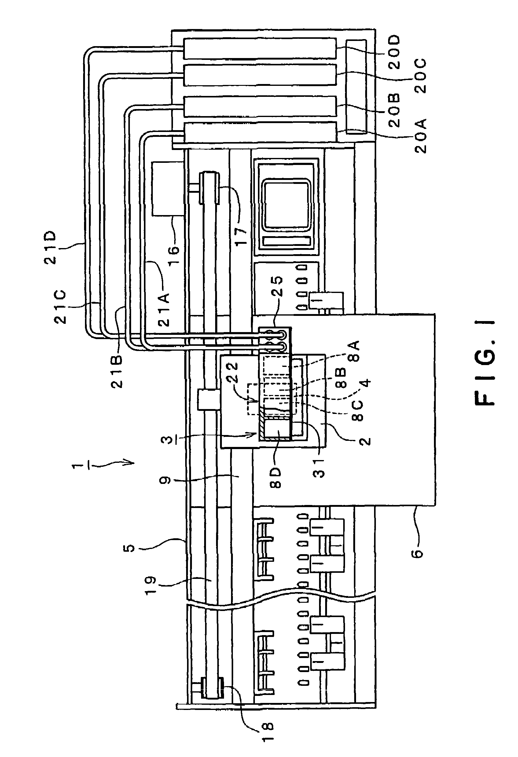
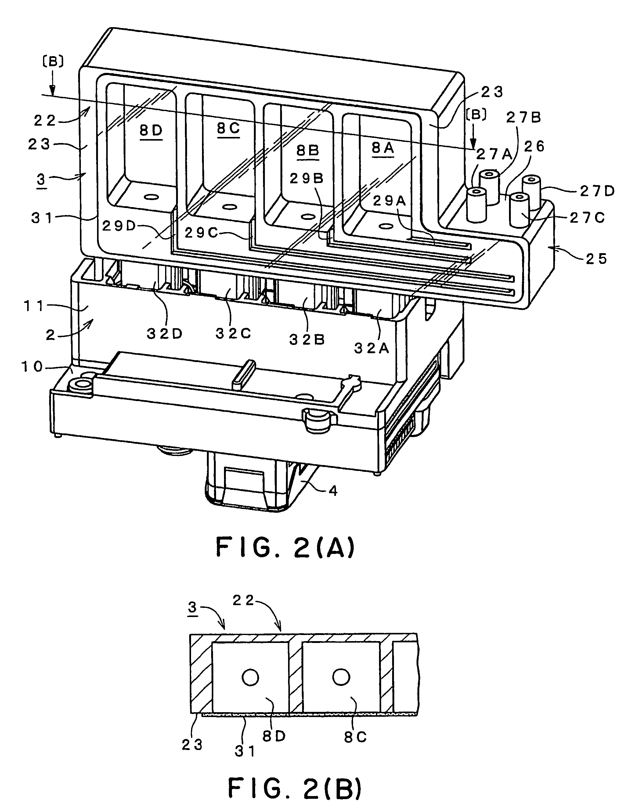
[0052]FIG. 1 is a schematic plan view of an ink-jetting printer 1 (hereinafter, referred to as printer 1) that is an ink-jetting recording apparatus as a first embodiment according to the invention. FIG. 2(A) is a perspective view of a carriage 2 seen from an obliquely upside thereof. FIG. 2(B) is a sectional view taken along a line B-B of FIG. 2(A). FIG. 3(A) is a longitudinal sectional view of the carriage 2 and a sub tank 3. FIG. 3(B) is a sectional view taken along a line B-B of FIG. 3(A). FIG. 3(C) is a sectional view taken along a line C-C of FIG. 3(A).
[0053]As shown in FIG. 1, the printer 1 is mainly formed by the carriage 2 and a printer main body 5, the sub tank 3 and a recording head 4 being mounted on the carriage 2. In the printer main body 5, provided are a head scanning mechanism that causes the carriage 2 to reciprocate in a main scanning direction, a paper feeding mechanism that feeds a recording paper 6 in a paper-feeding direction, a recovering mechanism that recov...
second embodiment
[0073]Next, FIG. 4 is a perspective view of a carriage in an ink-jetting recording apparatus of a second embodiment according to the invention.
[0074]In the second embodiment, mounting posture of the sub tank 3 is set in such a manner that the edge surface 23 is substantially horizontal. Then, the cylindrical needle-connection parts, not shown, are arranged on a side opposite to the elastic sheet 31. The other structures are substantially the same as the first embodiment. The same parts are represented by the same numeral signs, and explanation thereof is omitted.
[0075]When the above structure is adopted, a depth of the ink storing rooms 8A, 8B, 8C, 8D in a perpendicular direction with respect to the elastic sheet 31 may be made smaller, so that dimensions of the sub tank 3 in the perpendicular (vertical) direction may be made small. Thus, an occupancy space required near the carriage 2 may be reduced.
third embodiment
[0076]Next, FIGS. 5(A) to 5(C) are views showing a sub tank in a third embodiment according to the invention.
[0077]In the present embodiment, the ink-storing-room openings are also open at a flat reverse edge surface 34, oppositely to the edge surface 23. A second elastic sheet 31′ is jointed to the reverse edge surface 34. The other structures are substantially the same as the first embodiment. The same parts are represented by the same numeral signs, and explanation thereof is omitted.
[0078]In the above structure, the respective ink storing rooms 8A, 8B, 8C, 8D can have the elastic sheets 31, 31′ at the two surfaces. Thus, effective areas of the elastic sheets 31, 31′ may be made as large as possible, so that a volume of each liquid storing room 8A, 8B, 8C, 8D may be made as small as possible. Thus, the sub tank 3 may be made more compact, which is effective in reducing required space and cost.
PUM
 Abstract
Description
Claims
Application Information
 - R&D
- Intellectual Property
- Life Sciences
- Materials
- Tech Scout
- Unparalleled Data Quality
- Higher Quality Content
- 60% Fewer Hallucinations
Browse by: Latest US Patents, China's latest patents, Technical Efficacy Thesaurus, Application Domain, Technology Topic, Popular Technical Reports.
© 2025 PatSnap. All rights reserved.Legal|Privacy policy|Modern Slavery Act Transparency Statement|Sitemap|About US| Contact US: help@patsnap.com


