Coating apparatus

a coating and granule technology, applied in the field of coating apparatuses, can solve the problems of reducing the product yield, affecting the quality of the coating, and the inside of the granule layer is not ventilated enough, so as to prevent wear and deterioration, prolong the sealing life, and accelerate the discharge of the granule products.

Inactive Publication Date: 2009-11-10
POWEREX
View PDF26 Cites 13 Cited by
  • Summary
  • Abstract
  • Description
  • Claims
  • Application Information

AI Technical Summary

Benefits of technology

[0022]An object of the present invention to provide a coating apparatus that is excellent in the ease of cleaning and validation after the cleaning.
[0023]Another object of the present invention is to provide a coating apparatus that is excellent in the quality and efficiency of the coating process.

Problems solved by technology

With such ventilation system, however, the process gas such as dry air makes contact only with the surface layer of the granule layer, because of which sufficient ventilation is not achieved to the inside of the granule layer.
Moreover, when performing validation on the inside of the ventilation channels after the cleaning, or when wiping off powder or the like of abraded granule particles adhered inside the ventilation channels, the jackets forming the ventilation channels must be removed and then mounted again after the completion of a required procedure, which is troublesome.
Adhesion of coating material on the inner wall of the rotating drum will cause a complex cleaning or validation process after the coating process, and also lead to a loss of the coating material and a decrease in the product yield.
The apparatuses thus entail the following problems: If the air vents of the supply pipe and exhaust pipe are located outside the granule layer, the process gas such as dry air cannot provide ventilation for the inside of the granule layer and it takes a long time to dry the granules, or, the granules may be dried unevenly, resulting in deterioration of the coating quality.
On the other hand, if the air vent of the supply pipe or exhaust pipe is embedded in the granule layer so as to resolve this problem, powder or the like of abraded granule particles or coating liquid may adhere to the supply pipe or exhaust pipe and clog the air vent, leading to ventilation failure and requiring a complex cleaning process after the coating process, or it may cause contamination.
Also, the supply pipe or exhaust pipe embedded inside will inhibit smooth flow of the granule layer and may cause deterioration of the coating quality.
With the coating apparatuses shown in Patent Documents 6 and 7, on the other hand, the rotating drum can be cooled or heated from outside, but if the rotating drum includes a baffle, sufficient cooling or heating of the baffle cannot be expected.
Thus there is a problem that coating material such as sugar liquid or chocolate paste tends to stick to the baffle.

Method used


Image

  • Coating apparatus
  • Coating apparatus
  • Coating apparatus

Examples


Embodiment Construction

[0066]Various embodiments of the present invention will be hereinafter described with reference to the accompanying drawings.

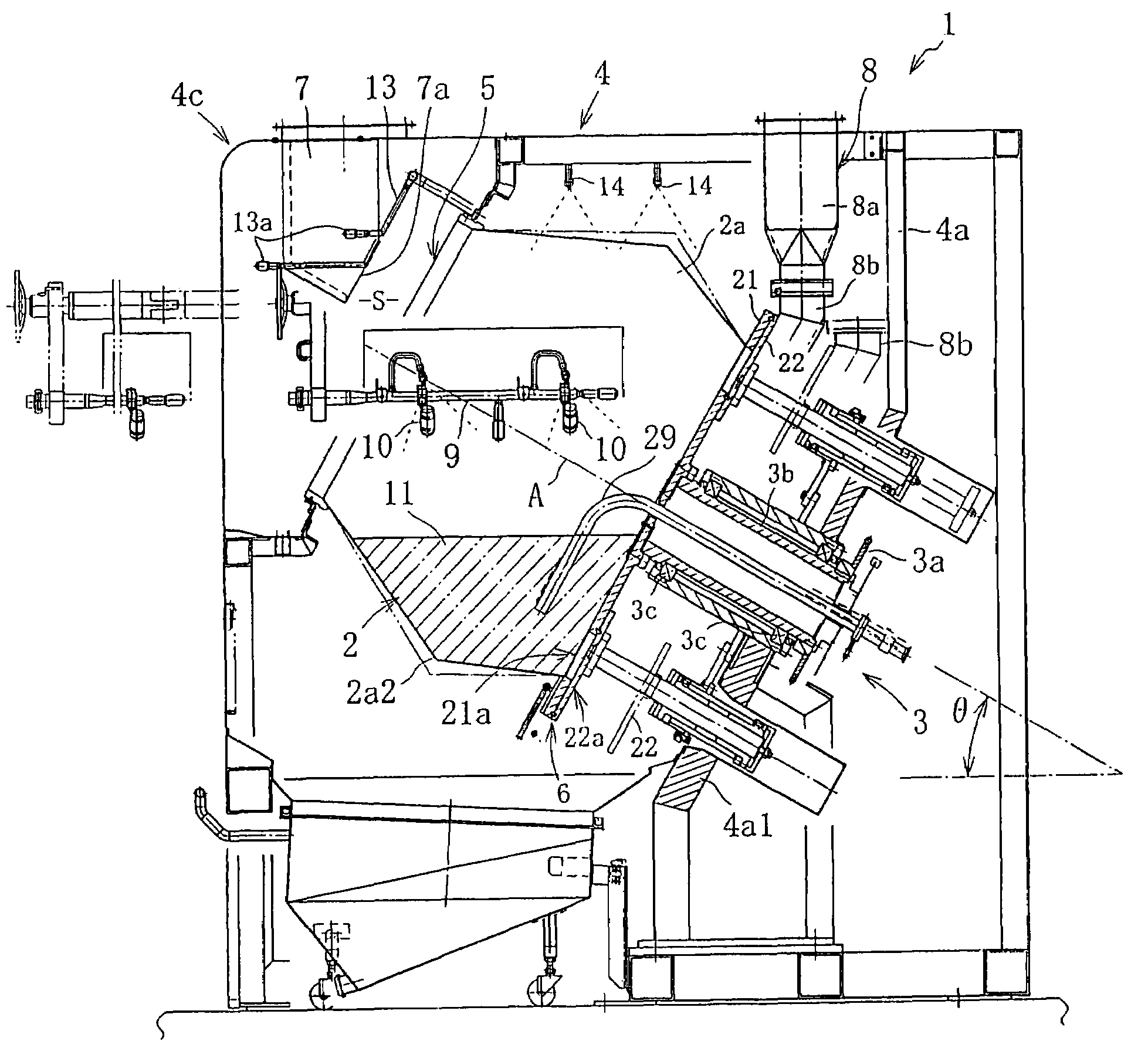
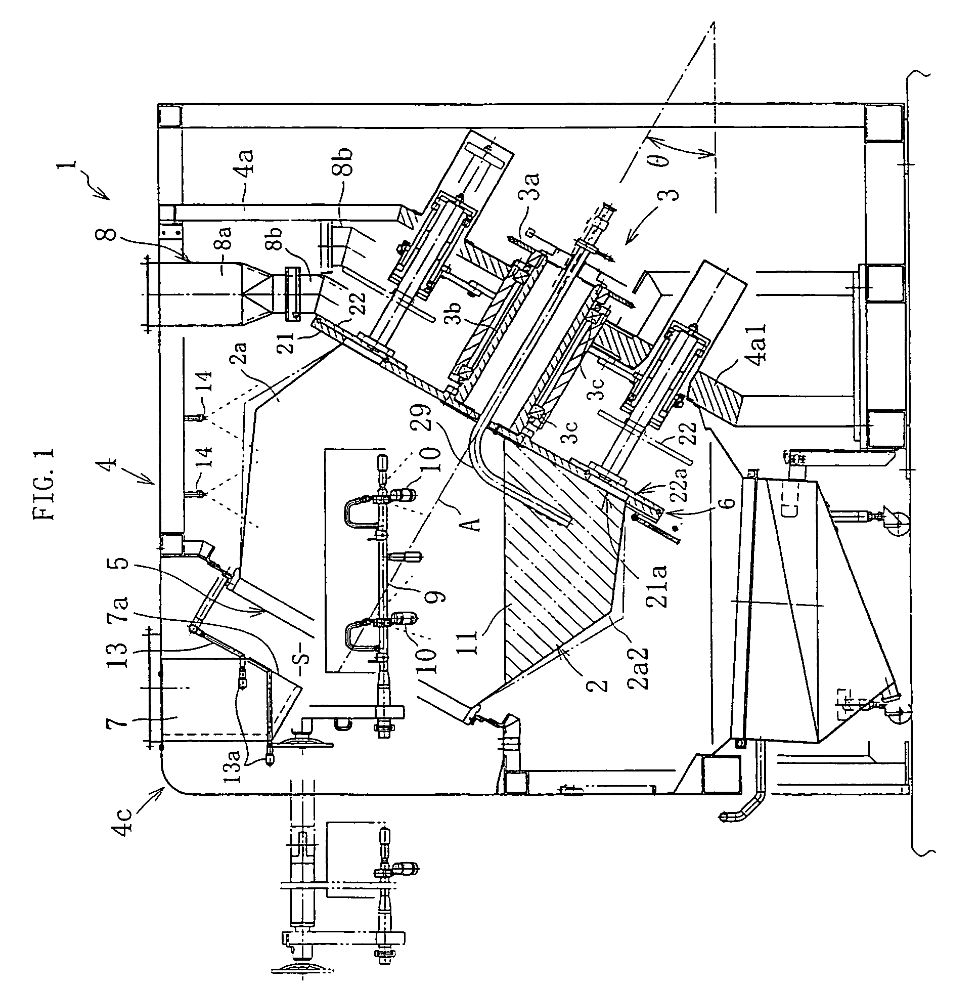
[0067]FIG. 1 shows a coating apparatus 1 according to a first embodiment. The coating apparatus 1 includes a rotating drum 2 disposed such as to be rotatable around an axial line A that is inclined to the horizontal at a preset angle θ of, for example, 30°, and a rotary drive mechanism 3 for driving the rotating drum 2 in forward and / or reverse directions; these rotating drum 2 and rotary drive mechanism 3 are accommodated inside a casing 4.

[0068]The rotary drive mechanism 3 has, by way of example, a construction that reduces the rotating force of a drive motor using a reduction gear and inputs the same to a hollow drive shaft 3b that is connected to the rear end, or the lower side end, of the inclined rotating drum 2, via a chain (not shown) and a sprocket 3a. In this construction, the drive shaft 3b and rotating drum 2 are rotatably supported by bearings 3c ...


PUM


Abstract

The rotating drum 2 rotates around an axial line A that is inclined to the horizontal at a present angle θ. Process gas flows in the rotating a drum 2 from an air vent 7a of an air duct 7 through an air inlet 5 at one end of the rotating drum 2, passes through a layer of granules 11, and flows out into an air outlet duct 8 through an air vent 21a of a first disc plate 21 and a connection hole 22a in a second disc plate 22.

Description

BACKGROUND OF THE INVENTION[0001]The present invention relates to a coating apparatus for performing coating, mixing, drying, and the like of medical, food, pesticidal products, and the like that are in granular form, and more particularly to a coating apparatus having a rotating drum that is driven to rotate around its axial line.[0002]Coating apparatus having a rotating drum has been used or performing film coating, sugar coating, and the like to medical, food, pesticidal products, and the like that are prepared as tablets, soft capsules, pellets, grains, and in other similar forms (hereinafter collectively referred to as “granules”).[0003]The following Patent Documents 1 to 7, for example, disclose this type of coating apparatus.[0004]Patent Document 1 discloses a coating apparatus having a ventilated rotating drum 30 driven to rotate around a horizontal axial line A, as shown in FIG. 18. The rotating drum 30 is composed of a polygonal tube peripheral wall 30c, one end wall 30a f...

Claims


Application Information

Patent Timeline
Patent Type & Authority Patents(United States)
IPC IPC(8): B05C3/08B05B13/02B05B15/02B05B15/12
CPCB05B13/0257
Inventor HASEGAWAMATSUURA, HIROSHIMURAKAMI, TETSUYASAKAMOTO, TAKASHI
Owner POWEREX
Why Eureka
Try Eureka