Temperature control device

a temperature control and temperature technology, applied in the direction of indirect heat exchangers, lighting and heating apparatus, domestic cooling apparatus, etc., can solve the problems of difficult efficient heat exchange between, long time for stabilizing the temperature of liquid chemical, etc., to achieve convenient and quick temperature control, efficient heat exchange, and easy formation of a long circulation passage

Active Publication Date: 2009-10-27
SMC CORP
View PDF9 Cites 7 Cited by
  • Summary
  • Abstract
  • Description
  • Claims
  • Application Information

AI Technical Summary

Benefits of technology

[0007]Accordingly, it is an object of the present invention to provide a temperature control device capable of performing efficient heat exchange between a constant-temperature fluid under the temperature control and a liquid chemical subjected to the temperature control while reducing the size of the system, thus allowing easy and quick temperature control of the liquid chemical to the constant temperature.
[0008]It is another object of the present invention to provide a temperature control device that allows a space-saving long circulation channel to be easily formed within the liquid tank.
[0016]In the temperature control device with the aforementioned structure, the circulation passage is formed by arranging a plurality of screening cylinders each having a different diameter concentrically within the liquid tank. This makes it possible to easily form a long circulation passage for the heat exchange within the limited space inside the liquid tank. The aforementioned structure and the pump provided in the liquid tank for circulating the constant-temperature fluid along the circulation passage make it possible to appropriately raise the flow rate of the constant-temperature fluid flowing around the heat transfer tube within the circulation passage. Accordingly, the heat exchange between the constant-temperature fluid and the liquid chemical flowing through the heat transfer tube may be efficiently performed, resulting in easy and quick temperature control of the liquid chemical to the constant temperature.
[0017]In this manner, the temperature control device according to the present invention is capable of performing efficient heat exchange between the constant-temperature fluid under the temperature control and the liquid chemical subjected to the temperature control while reducing the size of the system, resulting in easy and quick temperature control of the liquid chemical to the constant temperature. Also, the long circulation passage may be easily formed within the liquid tank while saving the space of the system.

Problems solved by technology

It is, thus, difficult to efficiently perform the heat exchange between the liquid chemical flowing through the coil tube and the heat exchange medium.
This may cause the problem of taking much time for stabilizing the temperature of the liquid chemical.

Method used


Image

  • Temperature control device
  • Temperature control device
  • Temperature control device

Examples


first embodiment

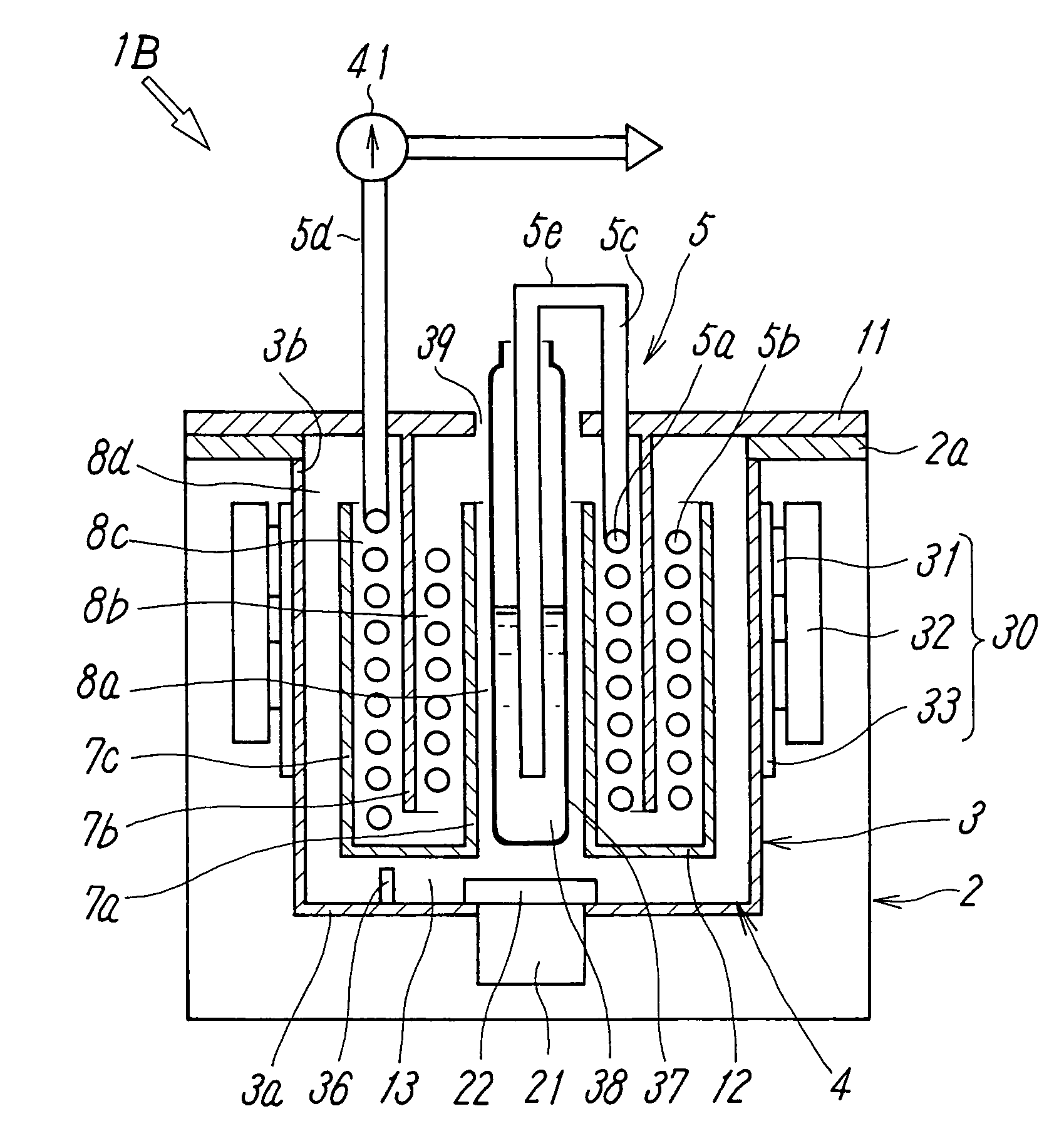
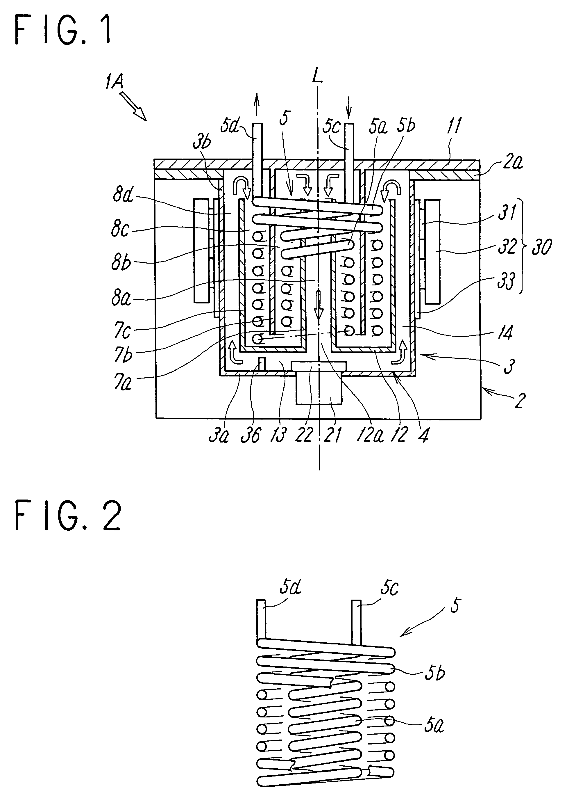
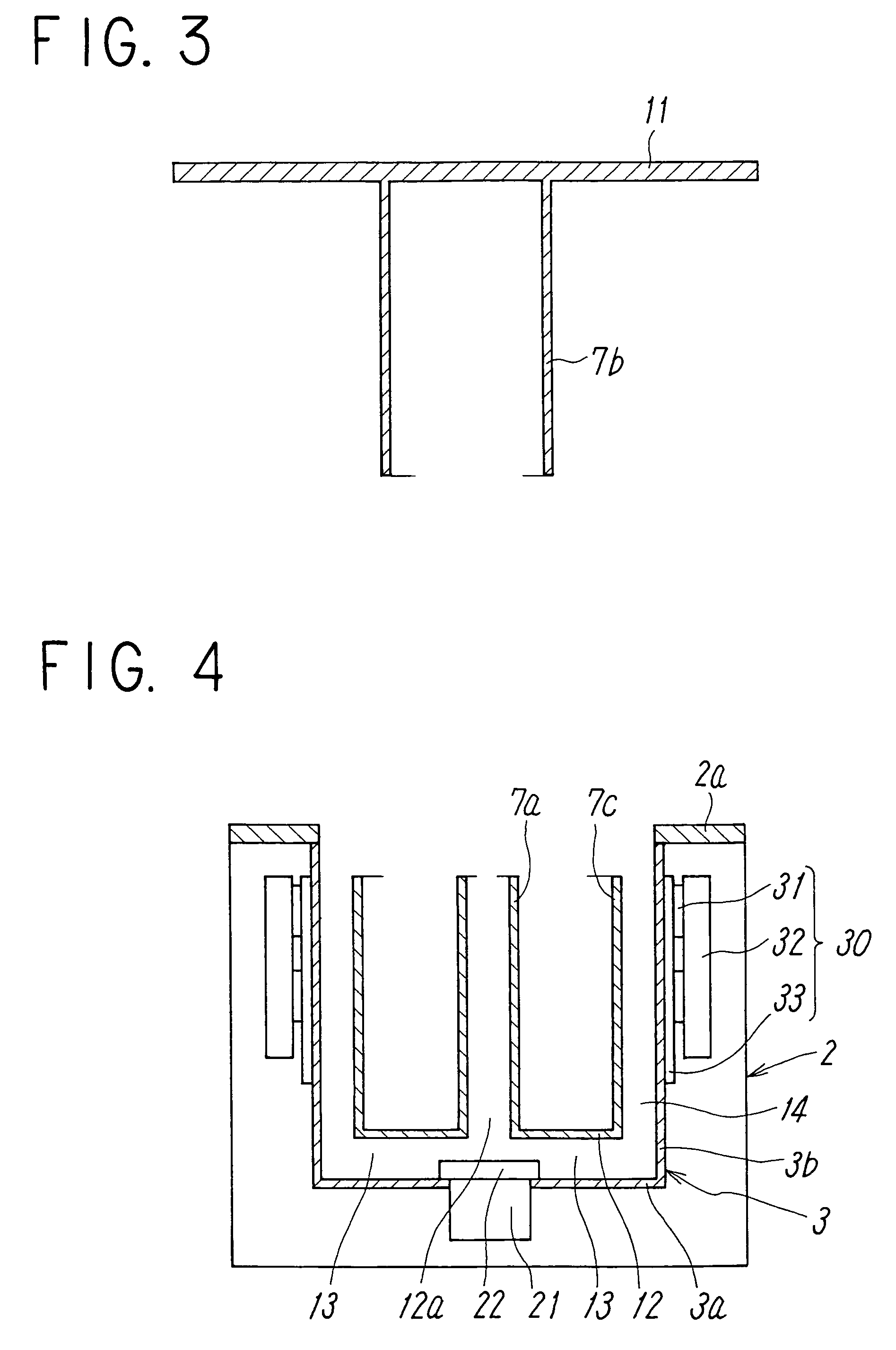
[0026]FIGS. 1 to 4 show a temperature control device according to the present invention. A temperature control device 1A is provided with a liquid tank 3 in which temperature-constant fluid contained therein is controlled to a constant temperature by a heat exchanger 30 equipped with a thermo-module 31, a circulation passage 4 formed within the liquid tank 3 that allows the temperature-constant fluid to flow therethrough, a heat transfer tube 5 including spiral heat transfer coils 5a and 5b provided within the circulation passage 4, a casing 2 that contains the liquid tank 3, and a pump 21 disposed at the center of a bottom wall 3a of the liquid tank 3 for circulating the constant-temperature fluid along the circulation passage 4.

[0027]In FIG. 1, the direction of the liquid chemical flowing through the heat transfer tube 5 is illustrated by thin arrows, and the direction of the constant-temperature fluid circulating through the circulation passage is illustrated by an outline arrow,...

second embodiment

[0045]In the second embodiment, the liquid chemical in the container 37 within the screening cylinder 7a may be preliminarily subjected to the temperature control, thus further improving efficiency in the temperature control.

[0046]Since the other structure and operation of the second embodiment are the same as those of the first embodiment as shown in FIG. 1, the same elements as those of the first embodiment will be designated with the same reference numerals, and explanations thereof, thus will be omitted.

[0047]FIG. 6 shows a temperature control device according to a third embodiment of the present invention. Likewise the first embodiment, the temperature control device 1C has a plurality of layered channels 8a to 8d defined by the plurality of screening cylinders 7a to 7c in the liquid tank 3. The aforementioned channels 8a to 8d and the communication passage 13 form the circulation passage 4. However, the structure of the heat transfer tube 5 is different from that of the first ...


PUM


Abstract

In a temperature control device, a plurality of screening cylinders each having a different diameter are concentrically arranged within a liquid tank to concentrically form a plurality of layered channels which are communicated to define a circulation passage through which constant-temperature fluid flows. A heat transfer tube through which liquid chemical flows is disposed in any one of the channels such that heat exchange between the liquid chemical and the constant-temperature fluid is performed via the heat transfer tube for controlling temperatures of the liquid chemical.

Description

TECHNICAL FIELD[0001]The present invention relates to a temperature control device provided with a circulation passage that allows constant-temperature fluid to flow circularly therethrough and a heat transfer tube provided in the circulation passage and allows a liquid chemical to flow therethrough for exchanging heat between the constant-temperature fluid and the liquid chemical via the heat transfer tube so as to control liquid chemical temperatures.BACKGROUND ART[0002]A temperature control system that includes a liquid tank which keeps the contents thereof at a constant temperature has been widely used. Recently, in a certain type of the temperature control device, a heat exchanger equipped with a thermo-module that controls temperatures using Peltier effect has been provided for the liquid tank (for example, see Japanese Unexamined Patent Application Publication No. 2000-75935). The heat exchanger equipped with the thermo-module is capable of switching the temperature control b...

Claims


Application Information

Patent Timeline
Patent Type & Authority Patents(United States)
IPC IPC(8): F28D7/10
CPCF28F27/00F28D7/024F25B21/04F25D31/002G05D23/08
Inventor SAIKA, MASAOHARADA, TAKAYUKIONO, TAKAHIRO
Owner SMC CORP
Why Eureka
Try Eureka