
Wavelength-division-multiplexing optical transmission system and control method thereof

a transmission system and optical transmission technology, applied in the direction of transmission monitoring, electromagnetic repeaters, instruments, etc., can solve the problems of inability to handle the fluctuation of the pre-amp output level (oadm input level) caused, the output level per wave becomes too large, and the optical input level fluctuation is too larg

Inactive Publication Date: 2009-10-20
FUJITSU LTD
View PDF8 Cites 9 Cited by
  • Summary
  • Abstract
  • Description
  • Claims
  • Application Information

AI Technical Summary

Benefits of technology

[0009]Taking the above into consideration, the object of the present invention is to keep the difference between the output level of the optical amplifier and the proper level that corresponds to the actual number of channels when a change in the number of channels occurs within a range in which signal-transmission error does not occur, even when level control is performed in addition to constant-gain control.
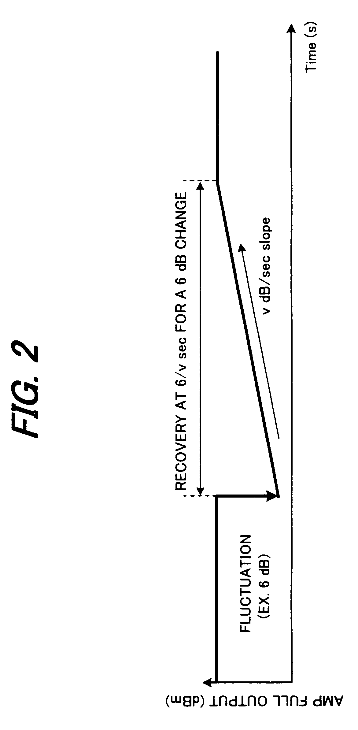
[0010]Taking into consideration the fluctuation allowance of the overall transmission system, another object of the present invention is to keep a period T from the time when the number of channels actually changes until constant-gain control is performed, or the level-recovery speed v of the optical amplifier at a value so that signal-transmission error does not occur when the number of channels changes.
[0016]According to this invention, the optical transmission system is controlled so that the equationT<Y / (N·v)is satisfied, wherein T denotes a period from the time when a change in the number of multiplexed wavelengths occurs until the constant-gain control starts v denotes output-level-recovery speed of the optical amplifier, Y denotes fluctuation allowance of a receiving unit after wavelength-division-multiplexing transmission, and N denotes a maximum number of spans, so it is possible to keep the difference between the actual output from the optical amplifier when there is a change in the number of multiplexed wavelengths and the proper level that corresponds to the number of multiplexed wavelengths within a range so that signal-transmission error does not occur.
[0017]According to this invention, by taking into consideration the fluctuation allowance of the overall transmission system, it is possible to determine a period T from the time when a change in the number of multiplexed wavelengths occurs until constant-gain control starts, or the output-level-recovery speed v, so it is possible to prevent signal-transmission error from occurring when there is a change in the number of multiplexed wavelengths.
[0018]According to this invention, a channel monitor that is located inside the optical-node apparatus beforehand is used to monitor the number of multiplexed wavelengths, so construction is simple.
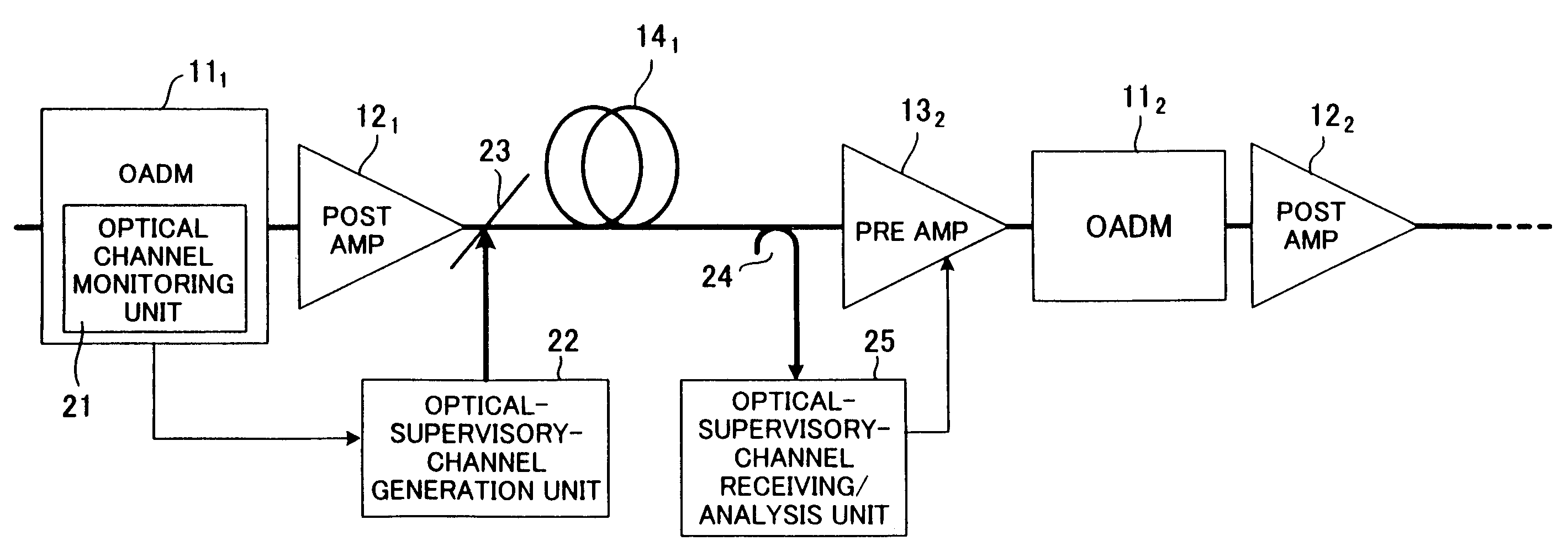
[0019]According to this invention, the number of multiplexed wavelengths at an upstream node is monitored, and using a monitoring-signal light having a wavelength that differs from a main signal light, or a low-frequency signal, it is possible to transmit the number of multiplexed wavelengths very quickly to a downstream pre amp. Therefore, it is possible to construct an optical transmission system that is able to satisfy the equation above.

Problems solved by technology

By using an optical amp for performing constant-optical-gain control in this way, it is possible to even out the wavelength characteristic, however, as shown in (B) of FIG. 14, it is not possible to handle the fluctuation in the pre-amp output level (OADM input level) caused by the fluctuation of transmission-path loss La, Lb, Lc.
However, in the prior constant-level control shown in FIG. 15, it is not determined whether the fluctuation in the optical-input level is due to a change in the number of channels, or due to loss fluctuation of the transmission path.
Therefore, in the prior constant-level control, control is performed to bring the output level to a set level even when the number of multiplexed wavelengths (number of channels) decreases, and thus the input level becomes low, so the output level per wave becomes too large, and signal-transmission error occurs.
Also, in the prior constant-level control, control is performed to keep the output level constant even when the number of channels increases, so the output level per wave becomes low and signal-transmission error occurs.
Therefore, during the period until level control starts according to the actual number of channels, and particularly, during the period that constant-gain control is performed, signal-transmission error occurs.

Method used


Image

  • Wavelength-division-multiplexing optical transmission system and control method thereof
  • Wavelength-division-multiplexing optical transmission system and control method thereof
  • Wavelength-division-multiplexing optical transmission system and control method thereof

Examples


Embodiment Construction

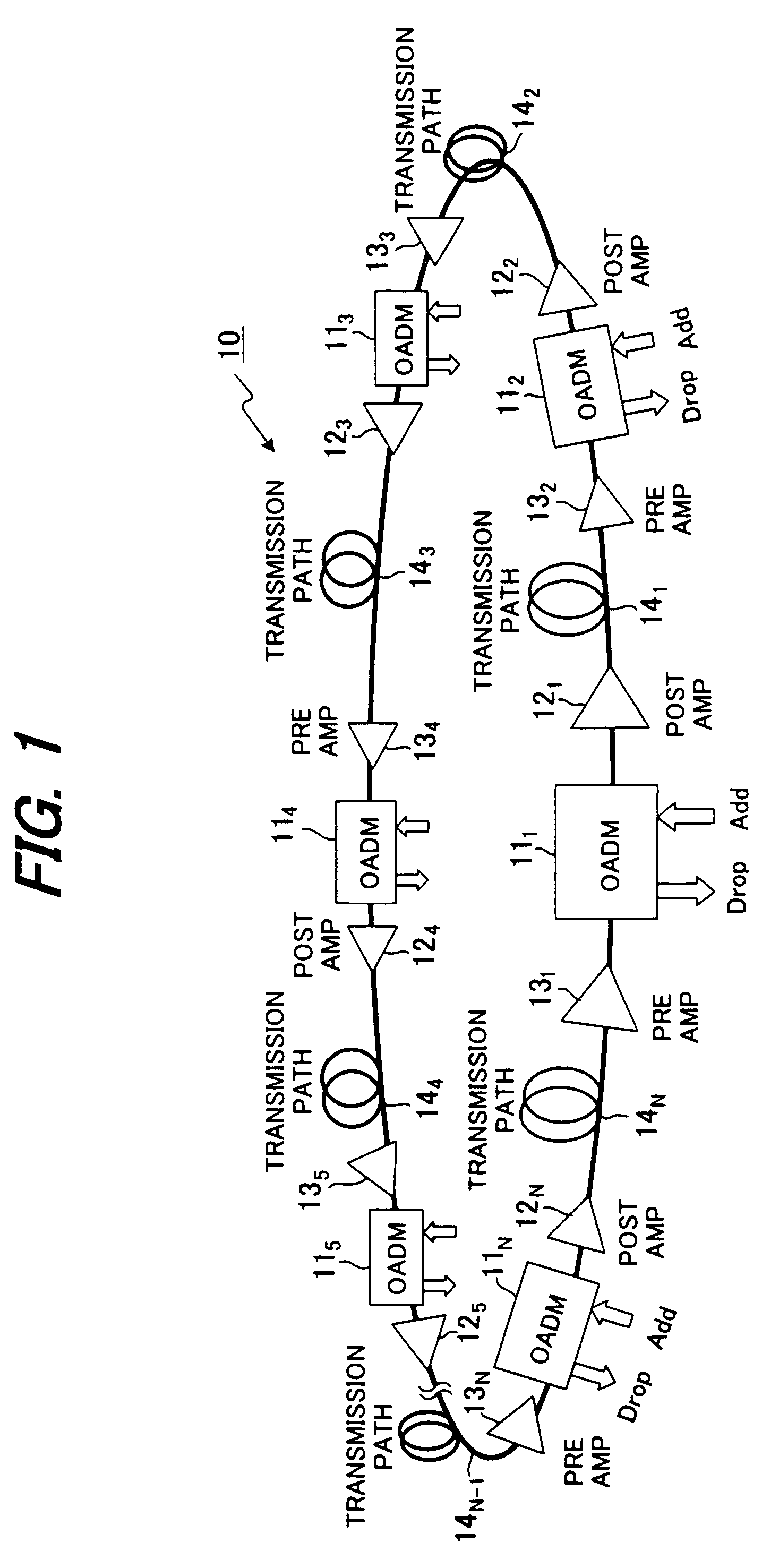
[0035]FIG. 1 is a drawing of a wavelength-division-multiplexing optical transmission system to which the present invention can be applied, and in that system N number of optical-node apparatuses (OADM) 111, 112, . . . , 11N that perform relay transmission of wavelength division multiplexed light (WDM signal light) are placed at appropriate locations (nodes) along the main optical transmission path 10. The main optical transmission path 10 is constructed so that it is ring shaped; therefore, by defining the space between adjacent OADM as a span, the number of spans and the number of OADM is the same, so there is N number of spans.

[0036]Each OADM 111, 112, . . . , 11N multiplexes data that is input from user terminals (not shown in the figure) under it on to the WDM signal light on the main optical transmission path 10 and transmits it (Add), or separates and extracts data for a user under it from the WDM signal light on the main optical transmission path 10 and transmits it to the us...


PUM


Abstract

In a wavelength-division-multiplexing optical transmission system in which optical-node apparatuses that perform relay transmission of wavelength-division-multiplexed light are located at specified nodes in a main optical transmission path, an optical amplifier switches level control to constant-gain control when there is a notification of a change in the number of multiplexed wavelengths, and then after a specified amount of time restarts level control so that the level becomes a target level that corresponds to the actual number of wavelengths. When doing this, an optical-transmission-system-control unit controls the optical-transmission system so that the equationT<Y / (N·v)is satisfied, wherein T denotes a period from the time when a change in the number of multiplexed wavelengths occurs until said constant-gain control starts v denotes output-level-recovery speed of the optical amplifier, Y denotes fluctuation allowance of a receiving unit after wavelength-division-multiplexing transmission, and N is a maximum number of spans.

Description

BACKGROUND OF THE INVENTION[0001]This invention relates to a wavelength-division-multiplexing optical transmission system and control method thereof, and particularly to a wavelength-division-multiplexing optical transmission system and control method thereof that comprises an optical-node apparatus that controls the optical level based on the number of multiplexed wavelengths,[0002]Wavelength-division-multiplexing (WDM) optical transmission that multiplexes a plurality of optical signals having different wavelengths in one optical fiber is a very effective method for performing a large volume of optical fiber communication. In the mainline of the wavelength-division-multiplexing optical transmission system, constant optical gain control is performed for the optical amp for prioritizing the level evenness characteristic of a wavelength. By performing this constant-optical-gain control it is possible to control the power per one wavelength (one channel) to be a fixed value even when ...

Claims


Application Information

Patent Timeline
Patent Type & Authority Patents(United States)
IPC IPC(8): H04B10/08H04B10/077H04B10/079H04B10/29H04B10/293H04B10/296H04B10/564H04B10/572H04J14/00H04J14/02
CPCH04J14/0221
Inventor SUGAYA, YASUSHI
Owner FUJITSU LTD
Learn More