
Network management system providing logic signals over communication lines for detecting peripheral devices

a network management system and logic signal technology, applied in the field of communication networks, can solve the problems of slow troubleshooting efforts, difficult to distinguish, and non-technical users may find it more difficult to get adequate troubleshooting assistance, and achieve the effect of attenuating communication signals

Active Publication Date: 2009-10-13
HEWLETT-PACKARD ENTERPRISE DEV LP +1
View PDF10 Cites 11 Cited by
  • Summary
  • Abstract
  • Description
  • Claims
  • Application Information

AI Technical Summary

Benefits of technology

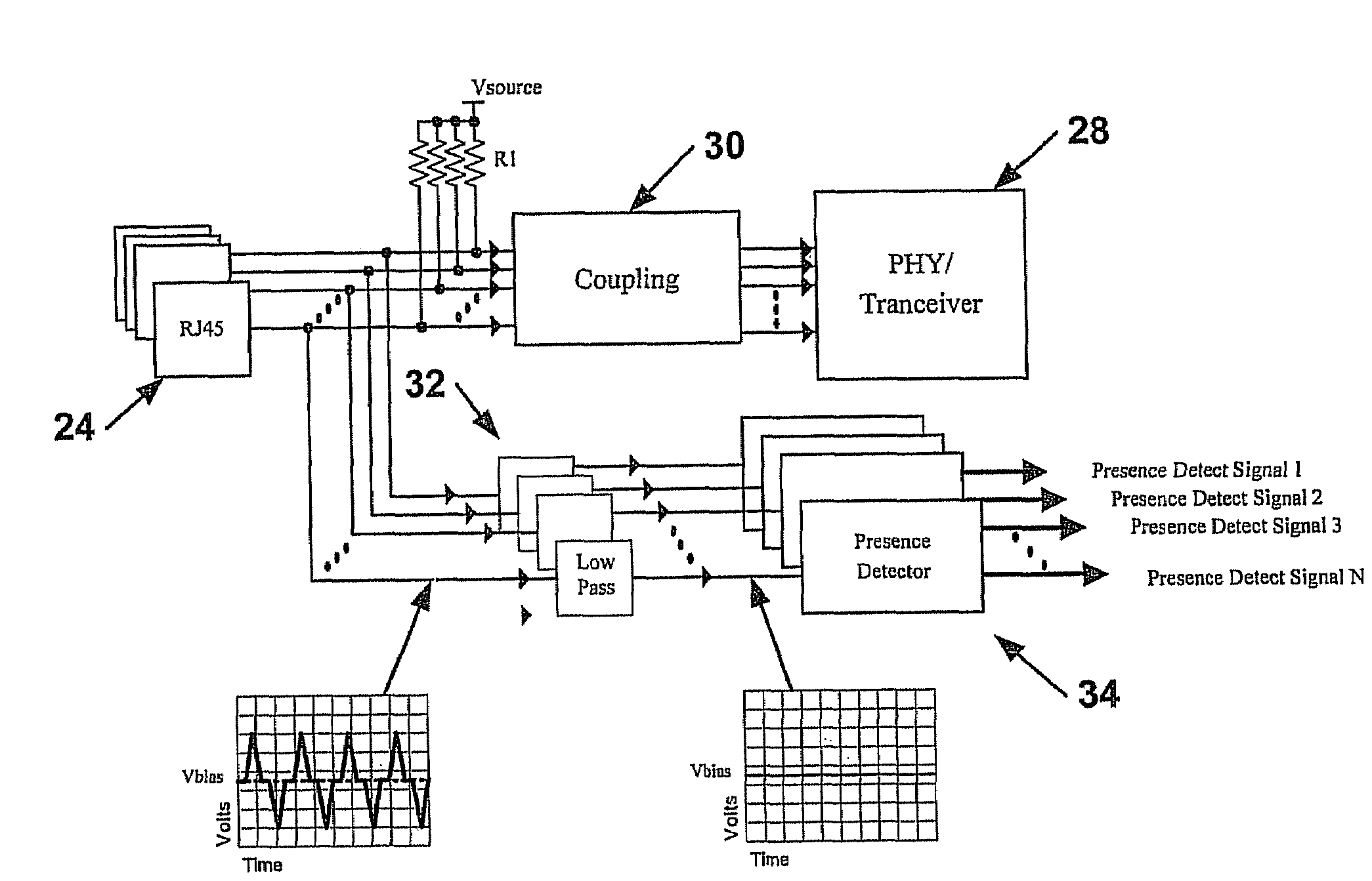
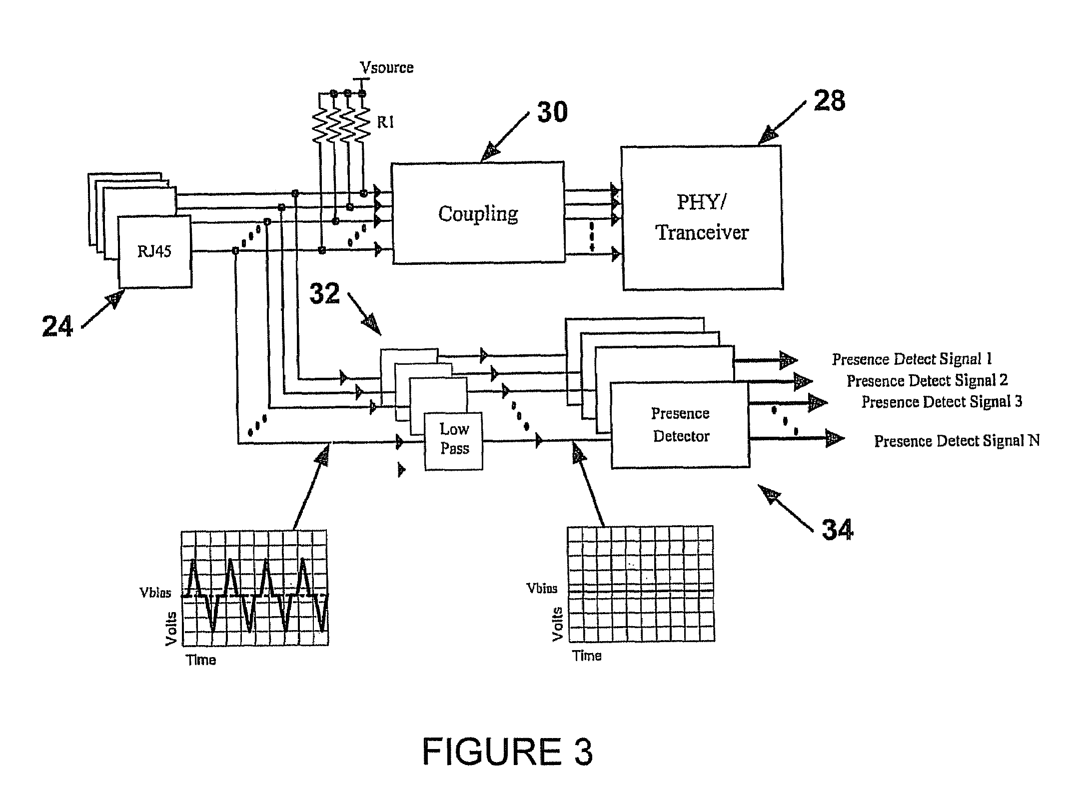
[0006]In one aspect, a method and system for detecting the presence of at least one network device coupled to a management device transceiver via a coupling and a transmission line is disclosed. The coupling provides communication signals from the management device transceiver to the transmission line. The method may include applying, through an impedance, a low-frequency voltage on the transmission line side of the coupling and coupling, via a filter, the low-frequency voltage on the transmis

Problems solved by technology

If a problem exists, it may be difficult to distinguish whether the cause is a bad cable, a bad connection, an unpowered device, a bad Ethernet interface, or another problem.
Even in cases where network devices are co-located with management devices in equipment racks, many presence detection systems cannot narrow possible problems, which can slow troubleshooting efforts.
In addition, in home networks, non-technical users may find it more difficult to get adequate troubleshooting assistance if they cannot isolate the cause of a problem at a basic level.

Method used


Image

  • Network management system providing logic signals over communication lines for detecting peripheral devices
  • Network management system providing logic signals over communication lines for detecting peripheral devices
  • Network management system providing logic signals over communication lines for detecting peripheral devices

Examples


Embodiment Construction

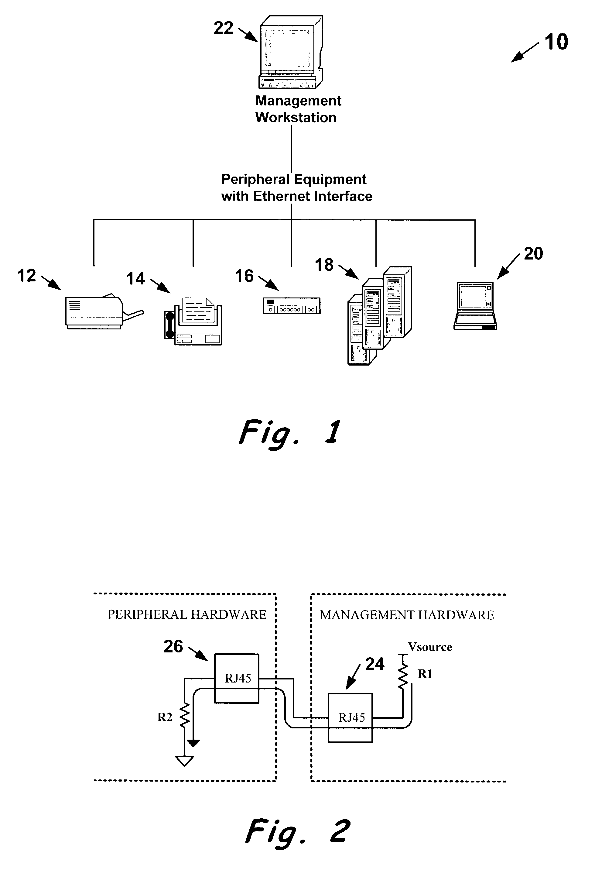
[0017]Referring now to the drawings, FIG. 1 shows a network 10 in which a presence detection system may be employed. The network 10 can include a number of communications devices illustrated, for example, by a printer 12, fax machine 14, hub 16, personal computers 18, and laptop computer 20. The communications devices can be connected to each other and to management workstation 22 via Ethernet or any other suitable network communication scheme.

[0018]Briefly, the system allows for automatic detection of devices present on the network 10 regardless of whether the devices are powered on or whether their communications hardware is functional. Although FIG. 1 illustrates a network comprising individual devices connected via point-to-point wiring, the system is equally applicable for detecting components, such as modem cards, that are interconnected via a backplane. Accordingly, twisted-pair cables and standard or special connectors, such as the RJ-45 connectors shown, could be replaced b...


PUM


Abstract

A method and apparatus for detecting the presence and the type of network devices connected to a management device via transmission lines. The apparatus may include a pull-up resistor, a pull-down resistor, a filter, and a presence detector, the resistors superimposing a DC or low-frequency voltage on the transmission line. The impact, if any, of the DC voltage one communications equipment and circuitry can be reduced by a coupling that isolates the DC voltage. Similarly, the filter prevents transmitted data signals from interfering with the DC voltage level. The method and apparatus function regardless of whether the network device is functional or powered on, and different values of pull-up or pull-down resistors can be used to indicate the type of device that terminates the transmission line.

Description

BACKGROUND OF THE SYSTEM[0001]1. Field of the Invention[0002]The present invention relates to communications networks, and, more particularly, to a method and apparatus for detecting the presence or absence of devices connected to communications networks.[0003]2. Description of Related Art[0004]Computer networks (such as Ethernet networks, for example) often use peripheral devices connected to a management workstation. In such networks, management hardware or software, or both, can typically detect the presence or absence of peripheral equipment only when the equipment is powered on and at least partially functional, since detection is done by recognizing received data having a known format. For example, standard Ethernet interfaces use link pulses and carrier sense for detecting equipment presence. Thus, standard detection schemes may require hardware on both ends of a communication link to have power; functional network interfaces; and good cables and connections. If a problem exi...

Claims


Application Information

Patent Timeline
IPC IPC(8): H04L29/00H04J99/00H04B3/50H04L12/24H04M1/00H04M1/76H04M3/00H04M7/00H04M9/00
CPCH04B3/50H04L43/0811
Inventor LE, LINH MYDIPERT, DWIGHT D.OSCHMANN, ELLEN
Owner HEWLETT-PACKARD ENTERPRISE DEV LP
Learn More