Imaging tomography apparatus with fluid-containing chambers forming out-of-balance compensating weights for a rotating part

a tomography apparatus and fluid-containing chamber technology, applied in tomography, applications, instruments, etc., can solve the problems of time-consuming and expensive procedures, inability to balance the measurement device of the tomography apparatus, and inability to achieve the effect of optimally balanced

Inactive Publication Date: 2009-10-13
SIEMENS HEALTHCARE GMBH
View PDF22 Cites 20 Cited by
  • Summary
  • Abstract
  • Description
  • Claims
  • Application Information

AI Technical Summary

Benefits of technology

[0017]Because the compensation weights are disposed in two parallel planes that are axially separated from one another, compensation of an out-of-balance condition caused by a non-uniform axial weight distribution is also possible. Wobbling movements thus can be compensated with this arrangement. Because at least two of the chambers in a plane are connected with at least one conduit, a compensation weight necessary for compensation of an out-of-balance condition can be adjusted in a simple manner by fluid transfer. The inventive arrangement can be controlled particularly simply. It is also possible for both of the opposite chambers to be connected with one another by means of two conduits. By a suitable connection of both conduits, centrifugal forces acting on the fluid can be compensated.
[0020]According to a further embodiment, a further sensor is provided to determine the rotation angle of the data acquisition device with regard to the stationary unit. This enables a particularly simple determination of the distribution of the compensation weights on the data acquisition device necessary for compensation of the out-of-balance condition.

Problems solved by technology

This procedure thus is time-consuming and expensive.
The implementation of these known methods typically requires technically trained personnel.
Independently of this, some of the known methods are not suited for balancing of a measurement device of a tomography apparatus.

Method used


Image

  • Imaging tomography apparatus with fluid-containing chambers forming out-of-balance compensating weights for a rotating part
  • Imaging tomography apparatus with fluid-containing chambers forming out-of-balance compensating weights for a rotating part
  • Imaging tomography apparatus with fluid-containing chambers forming out-of-balance compensating weights for a rotating part

Examples


Embodiment Construction

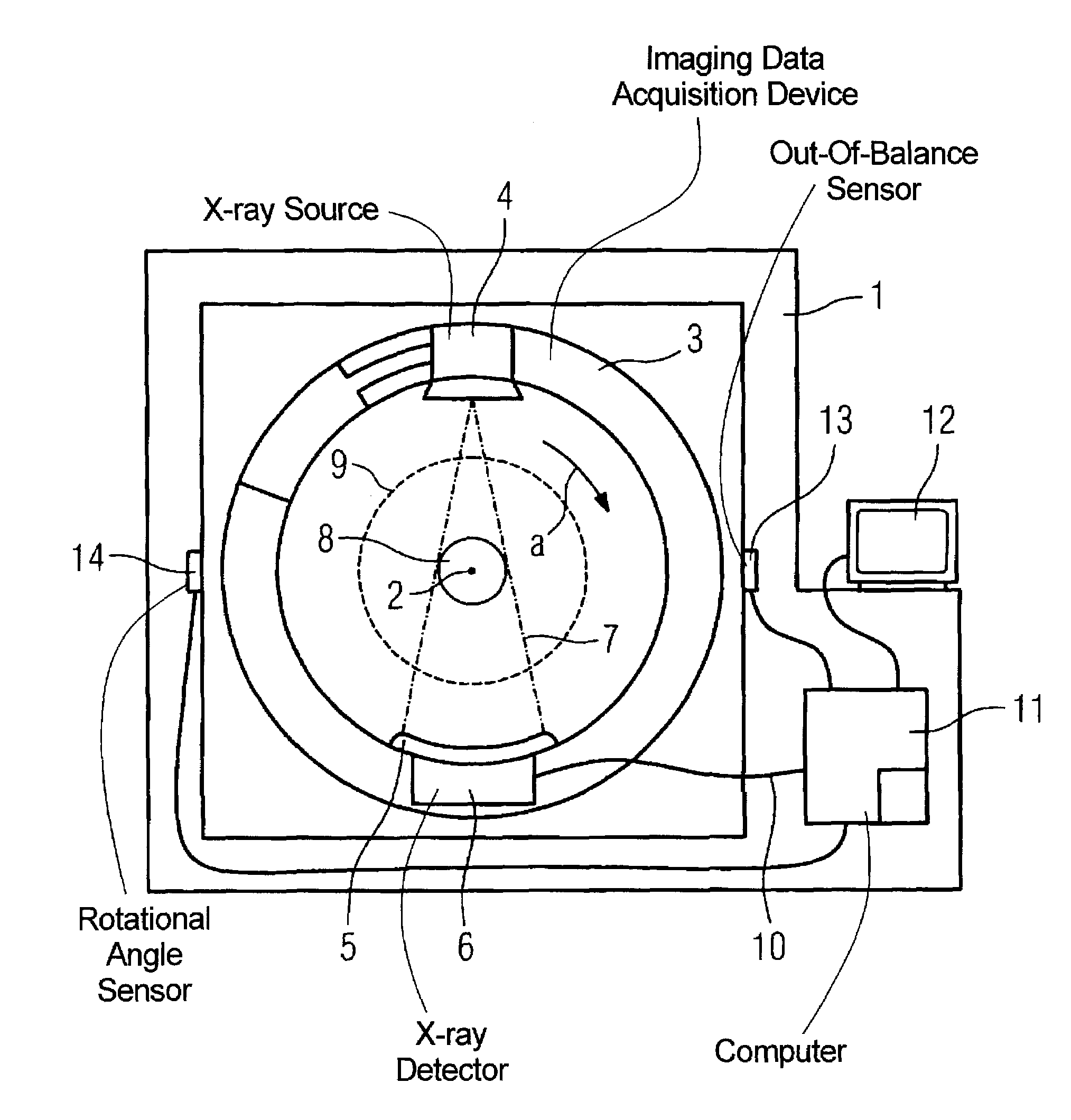
[0025]FIG. 1 schematically shows a side view of an x-ray tomography apparatus with a stationary unit 1. An annular imaging data acquisition device 3 (gantry) is accommodated on the stationary unit 1 such that it can rotate around a rotation axis 2 disposed at a right angle to the plane of the drawing. The rotation direction of the imaging data acquisition device 3 is designated with the arrow a. An x-ray source 4 and an x-ray detector 5 with downstream evaluation electronic 6 are mounted on the imaging data acquisition device 3 opposite to each other. A beam fan 7 radiated by the x-ray source 4 defines a circular measurement field 8 given a rotation of the imaging data acquisition device 3. The measurement field 8 is located within a patient opening 9 indicated with the dashed line. The evaluation electronic 6 is connected with a computer 11 via a slip ring contact 10 (indicated schematically). The computer 11 has a monitor 12 for display of data. A sensor 13 for measurement of vibr...


PUM


Abstract

An imaging tomography apparatus, in particular an x-ray tomography apparatus or an ultrasound tomography apparatus, has a stationary unit with a sensor for measurement of an out-of-balance condition of an annular data acquisition device rotatable around a patient opening in the stationary device. Compensation weights for compensation of the out-of-balance condition are provided on the data acquisition device. To simplify the balancing procedure, the compensation weights are disposed in two parallel planes axially separated from one another, and in each plane at least three compensation weights are fashioned as chambers that can be filled with a fluid. At least two of the chambers are connected with one another via at least one conduit for fluid transfer therebetween exchange.

Description

BACKGROUND OF THE INVENTION[0001]1. Field of the Invention[0002]The invention concerns an imaging tomography apparatus, in particular an x-ray computed tomography apparatus.[0003]2. Description of the Prior Art[0004]An x-ray computed tomography apparatus is known from German OS 101 08 065. A data acquisition device or gantry, mounted such that it can be rotated around a horizontal rotational axis, is accommodated in a stationary mount. A sensor to detect an out-of-balance (unbalanced) condition of the data acquisition device is provided on the stationary mount. The sensor is connected with a device to calculate the position or positions of the rotatable data acquisition device at which a compensation weight or weights should be applied to compensate the out-of-balance condition. The balancing can ensue without the use of a specific balancing device, but a trained person is required to implement the balancing procedure, in particular for correct application of the compensation weight...

Claims


Application Information

Patent Timeline
Patent Type & Authority Patents(United States)
IPC IPC(8): A61B5/00A61B6/00A61B6/03G01M1/36
CPCA61B6/035G01M1/365A61B6/586A61B6/447
Inventor DANZ, GUNTERMULLER, HANS-JURGEN
Owner SIEMENS HEALTHCARE GMBH
Why Eureka
Try Eureka