
System for replenishing energy sources onboard different types of automotive vehicles

a technology for automotive vehicles and energy sources, applied in special dispensing means, vessel mounting details, packaged goods types, etc., can solve the problems of slow pace, no service station or infrastructure to support the replenishment of such fuels or power sources, and the anticipated slow pace of developing and implementing such an alternative transportation infrastructur

Inactive Publication Date: 2009-10-13
CAPIZZO PETER DAVID
View PDF37 Cites 169 Cited by
  • Summary
  • Abstract
  • Description
  • Claims
  • Application Information

AI Technical Summary

Problems solved by technology

At the present time, however, a significant problem with utilizing hydrogen or any other type of alternative fuel or energy storage cell as a motivating power source onboard a vehicle is that there generally are no service stations or infrastructure to support the replenishing of such fuels or power sources.
That is, due to practical cost and inherent supply and demand matching concerns, such a pace is likely to be slow.
In particular, the anticipated slow pace in developing and implementing such an alternative transportation infrastructure is likely to be reinforced by several hindering factors.
Some of these factors may include, for example, the persistence of the oil industry even as it is somewhat phased out of operation (which may take many years), the high cost of the new fuel technology at low vehicle production volumes, and properly matching new vehicles' demand for such alternative fuels with service stations' capability to supply such alternative fuels.
With particular regard to the last factor, a transportation infrastructure with too few alternative fuel service stations will somewhat deter persons from purchasing alternative fuel vehicles and thus hinder the demand for alternative non-fossil fuels.
Also, if too few alternative fuel vehicles are purchased and operating on roadways, service station owners will then be slow to update their stations' infrastructures so as to accommodate such alternative fuel vehicles.
Furthermore, in addition to these hindering factors, as new vehicle technology is developed and introduced for operating on such alternative fuels, the operating characteristics of such new vehicle technology is likely to initially vary widely before preferred vehicle standards are commonly established.
This additional hindering factor thus initially works against establishing the complementary relationship that is generally necessary between infrastructure and alternative fuel type vehicles even more.
For example, as new vehicle technology is initially developed and introduced for operating on such alternative fuels or power sources, there will be occasions wherein a driver of a new hydrogen-fueled car cannot find a service station along his route of travel that can replenish his car's hydrogen level.
The disadvantage, however, in utilizing such retention materials is the characteristically slow re-hydrogenation rate that is associated therewith.
Such re-hydrogenation rates or times are generally comparable to that of the time required to recharge a battery in a battery-operated vehicle, and such an excessive amount of charging time has historically inhibited wide introduction and use of battery-operated vehicles.
In particular, when the battery of a battery-operated vehicle becomes discharged during use, the vehicle's driver must then discontinue driving the vehicle for a significant period of time while the vehicle's battery is recharged at a location with both a battery charger and space to park the vehicle (i.e., a charging site).
Such discontinuity in use of a battery-operated vehicle, however, is generally not practical for persons needing long-distance and / or frequent vehicle transportation.

Method used


Image

  • System for replenishing energy sources onboard different types of automotive vehicles
  • System for replenishing energy sources onboard different types of automotive vehicles
  • System for replenishing energy sources onboard different types of automotive vehicles

Examples


Embodiment Construction

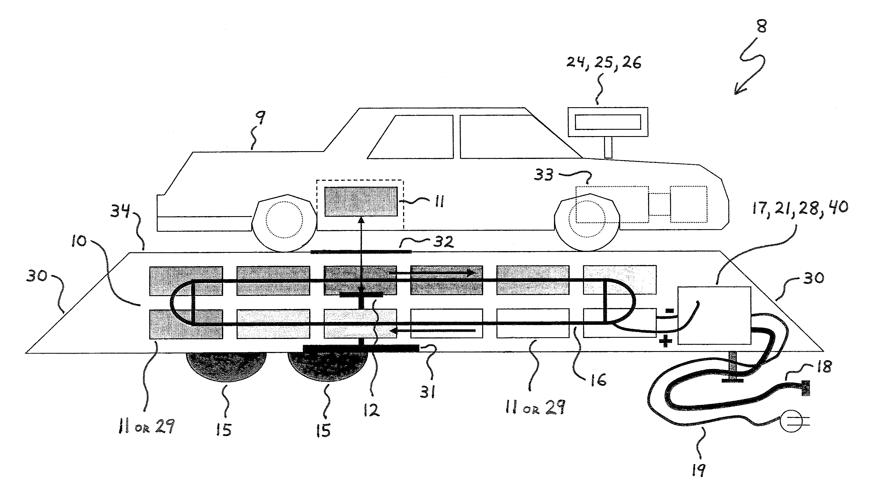
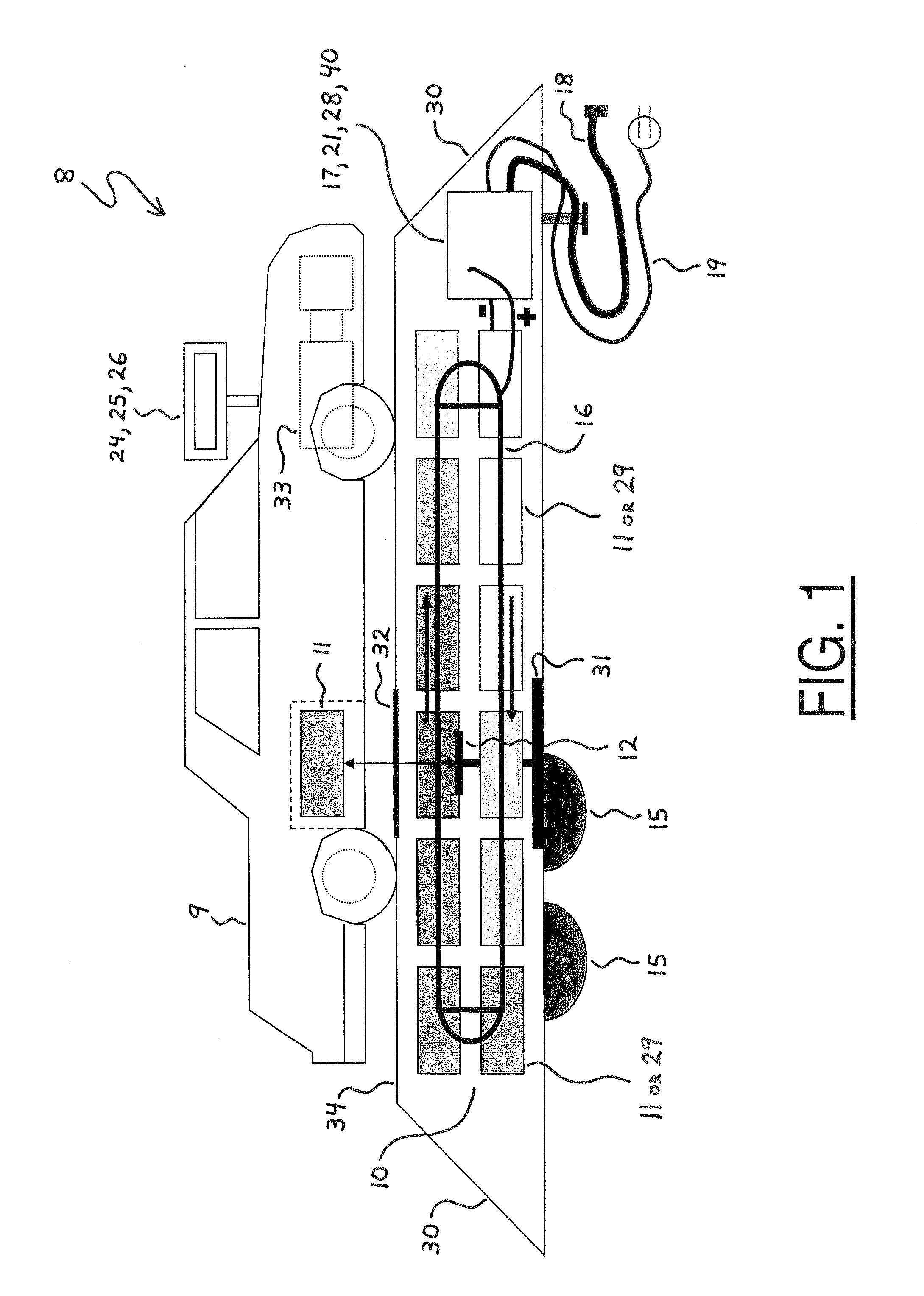
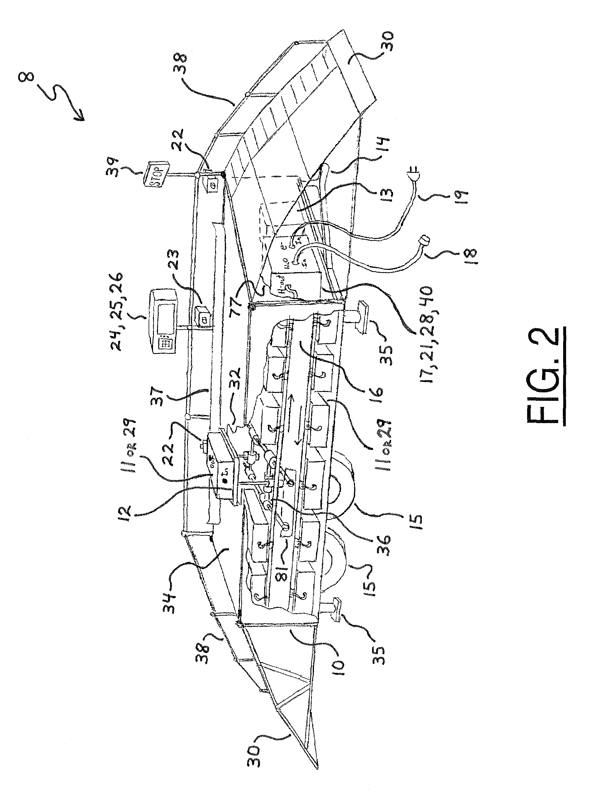
[0104]FIGS. 1 and 2 respectively illustrate side and perspective views of one practicable embodiment of a service station facility 8 pursuant to the present invention. In general, the service station facility 8 is adapted for replenishing various motivational energy sources onboard different types of automotive vehicles.

[0105]As shown in FIGS. 1 and 2, the service station facility 8 includes a rack 10, a plurality of replaceable fuel tanks 11, a robotic service module 12, and an electronic computer control system 13. The replaceable fuel tanks 11 are stocked on the rack 10 and substantially filled with various fluids utile as motivational energy sources within fuel-operated automotive vehicles. The robotic service module 12 is adjustably mounted on the rack 10 via a hydraulic lift system 31, a rack-and-pinion mechanism 36, and a rail system 81. The electronic computer control system 13 is connected in electrical communication with the robotic service module 12 and its adjusting syst...


PUM

PropertyMeasurementUnit
energyaaaaaaaaaa
densitiesaaaaaaaaaa
pressuresaaaaaaaaaa

Abstract

A service station facility for replenishing various motivational energy sources onboard different types of automotive vehicles is disclosed herein. In one embodiment, the service station facility includes a rack, replaceable fuel tanks, a service module, and an electronic computer control system. The replaceable fuel tanks are stocked on the rack and substantially filled with various fluids, such as hydrogen, which are utile as motivational energy sources within fuel-operated automotive vehicles. The service module is mounted on the rack, and the electronic computer control system is connected in electrical communication with the service module. In this configuration, the service module is controllably operable to receive a depleted replaceable fuel tank from a fuel-operated automotive vehicle and also selectively deliver one of the filled replaceable fuel tanks onboard the automotive vehicle. In another embodiment, the service station facility may also stock replaceable batteries for selective delivery onboard battery-operated automotive vehicles.

Description

CROSS REFERENCE TO A RELATED APPLICATION[0001]The present application claims priority to U.S. Provisional Application Ser. No. 60 / 733,472, filed on Nov. 4, 2005 and entitled “Portable Energy Rack for Inserting and Charging.”FIELD OF THE INVENTION[0002]The present invention generally relates to gas stations and service stations for automotive vehicles. The present invention more particularly relates to energy resource stations for different types of automotive vehicles such as, for example, electric, hydrogen, and fossil-fueled vehicles.BACKGROUND OF THE INVENTION[0003]In the future, as world oil supplies diminish or become more difficult to access, new types of fuels or energy storage cells such as batteries will have to be developed and integrated for use in automotive vehicles and also in the service stations of national transportation infrastructures. Though many alternative or replacement fuels are already currently under development, hydrogen fuel is presently considered by man...

Claims


Application Information

Patent Timeline
Patent Type & Authority Patents(United States)
IPC IPC(8): B60S5/06B65G67/02B67D7/04B67D7/24
CPCB60K15/063B60L11/1822B60L11/1838B60L11/1846B60L11/1848B60S5/00B60S5/02B60S5/06B67D7/0401F17C5/007G07F7/06B60K15/067B60L2200/26B60K2001/0472B60L2230/16Y02E60/321Y02T10/7005Y02T10/7011Y02T10/7016Y02T90/124Y02T90/128Y02T90/14Y02T90/16Y02T90/163Y02T90/169Y04S30/14Y02T10/7088Y02T90/121F17C2205/0192F17C2205/0364F17C2205/037F17C2221/012F17C2221/033F17C2221/035F17C2223/0153F17C2227/0135F17C2227/04F17C2250/032F17C2265/065F17C2270/0139F17C2270/0168F17C2270/0184G07F15/005B60L53/80B60L53/65B60L53/665B60L53/305B60L53/62B60L53/66Y02E60/32Y02T10/70Y02T10/7072Y02T90/12Y02T90/167
Inventor CAPIZZO, PETER DAVID
Owner CAPIZZO PETER DAVID
Learn More