
Apparatus and method for coding genetic information

a technology of genetic information and applicability, applied in the field of applicability and a method for coding genetic information, can solve the problems that the protocol differences cannot be reflected in the thermodynamic prediction model, and the conventional thermodynamic prediction model cannot be used as a prediction model for chips, so as to reduce the time and cost required for selecting the probes used on chips, the effect of rapid and accurate prediction results

Inactive Publication Date: 2009-10-06
SAMSUNG ELECTRONICS CO LTD
View PDF4 Cites 0 Cited by
  • Summary
  • Abstract
  • Description
  • Claims
  • Application Information

AI Technical Summary

Benefits of technology

The present invention provides an apparatus and method for coding genetic information to predict the results of DNA hybridization on various protocols. This allows for the creation of a prediction model that can be used for current protocols, reducing the time and cost required for selecting probes used on chips. The apparatus includes a data input unit, an aligning unit, a code storage unit, and a coding unit. The method involves aligning the genetic information, assigning first and second orthogonal codes to the bases, and adding flags to the codes to represent the presence or absence of a corresponding base or the type of genetic information. The technical effect is the creation of a reliable and efficient tool for predicting the results of DNA chip hybridization.

Problems solved by technology

However, since DNA hybridization in solutions differs from that occurring on the surfaces of matters such as chips, a conventional thermodynamic prediction model cannot be used as a prediction model for chips.
Also, differences in the protocol cannot be reflected in the thermodynamic prediction model.

Method used


Image

  • Apparatus and method for coding genetic information
  • Apparatus and method for coding genetic information
  • Apparatus and method for coding genetic information

Examples


Embodiment Construction

[0019]Hereinafter, preferred embodiments of an apparatus and a method for coding genetic information according to the present invention will be described in detail with reference to the accompanying drawings.

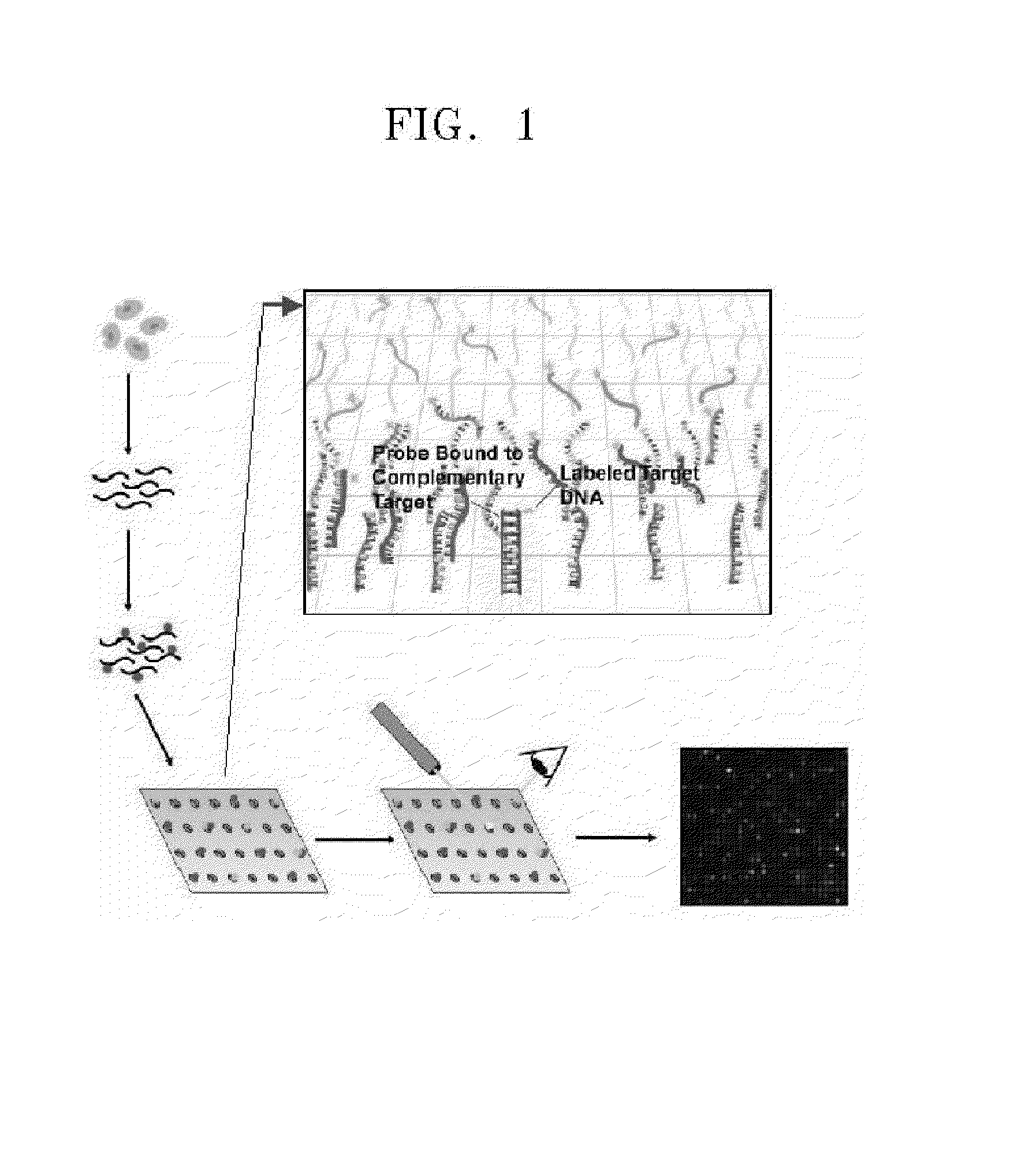
[0020]FIG. 1 is a diagram showing the principle of DNA chips.

[0021]When samples are placed on DNA chips having a plurality of probes, the samples are bound to probes having complementary base sequences. The degree of binding, i.e., hybridization between the probes and the samples, is assessed by the intensity of signal. In such DNA chips, the selection of optimal probes is an important factor that determines the performance of the DNA chips. Generally, probes used on DNA chips are selected by experiments, whereby significant time and cost are incurred.

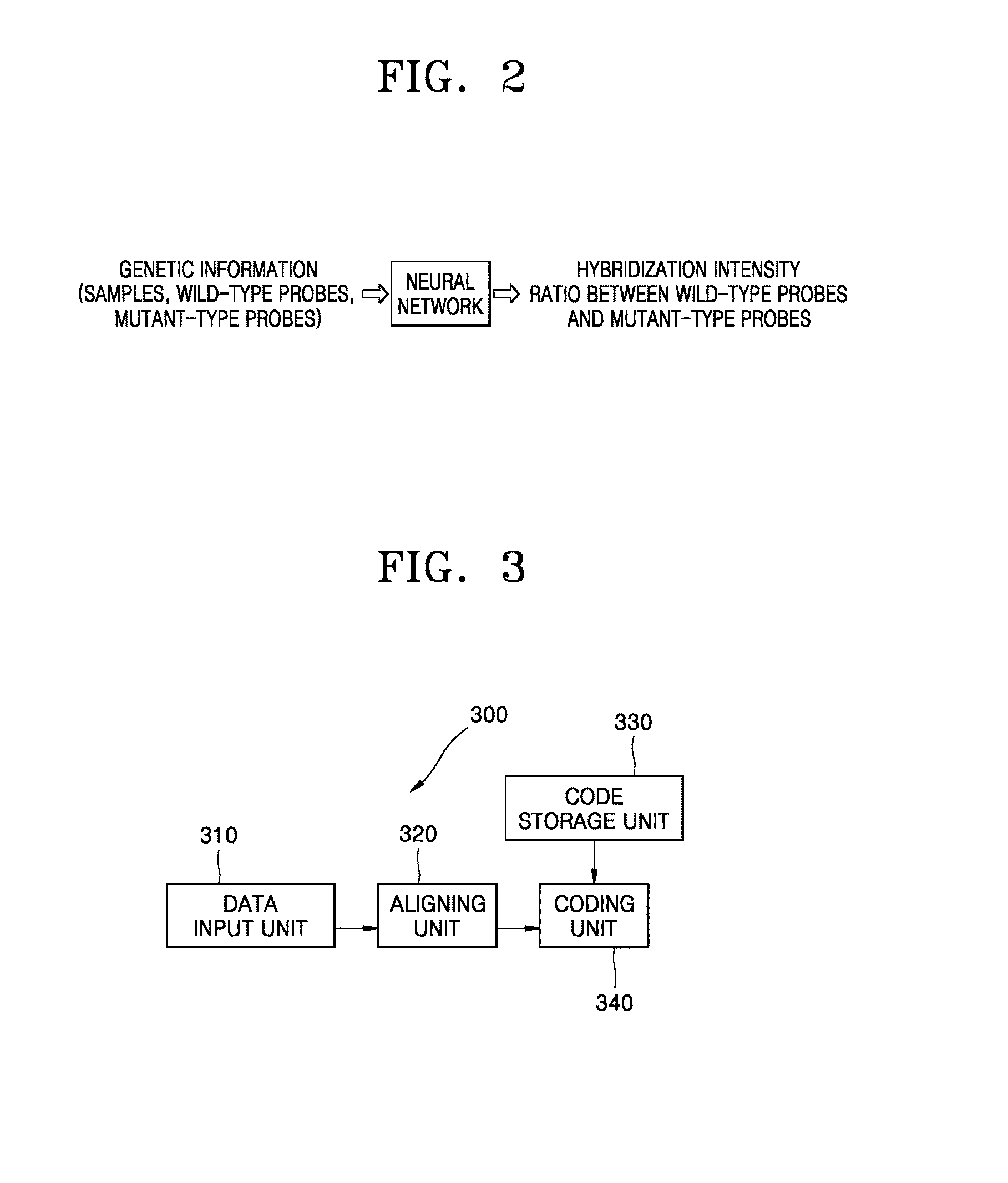
[0022]The present invention provides an apparatus and a method for coding genetic information to select probes that can be used on DNA chips. The genetic information coding apparatus and method are applied in neural networks using ...


PUM

PropertyMeasurementUnit
distancesaaaaaaaaaa
sizesaaaaaaaaaa
thermodynamic prediction modelaaaaaaaaaa

Abstract

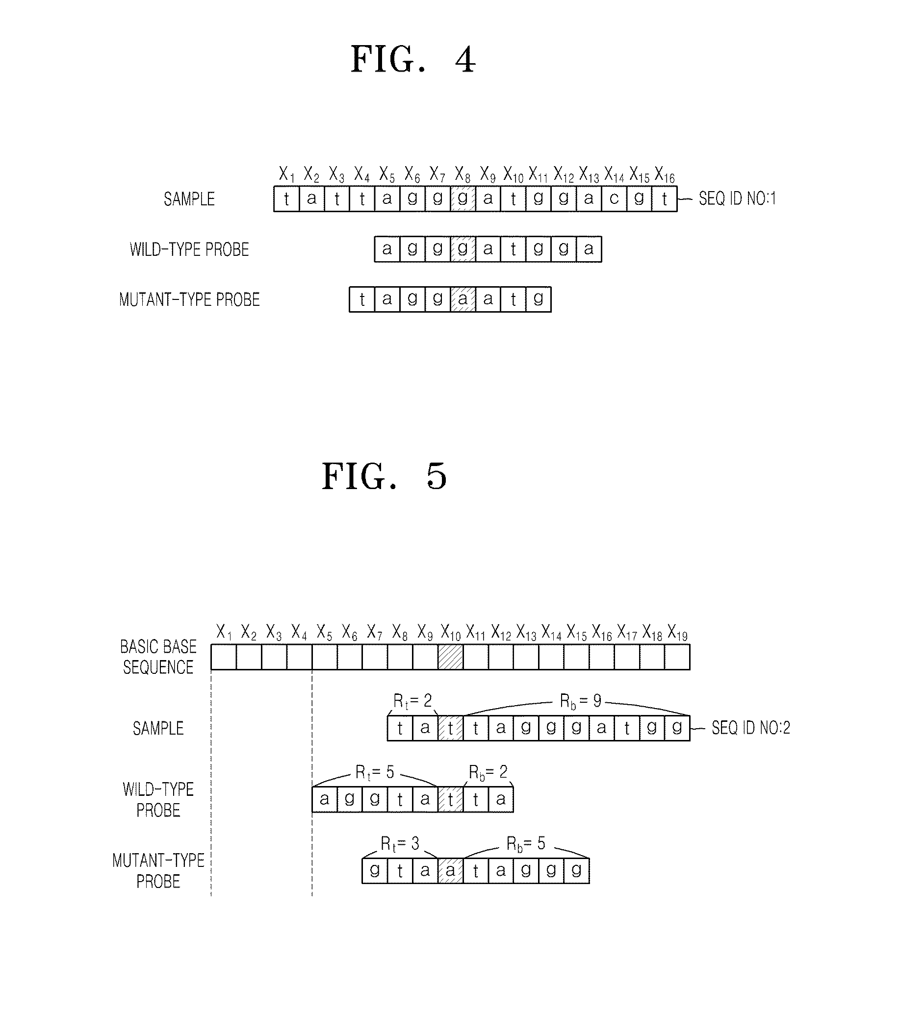
Provided are an apparatus and a method for coding genetic information. An aligning unit aligns sample genetic information, wild-type probe genetic information, and mutant-type probe genetic information, based on a mutation position. A code storage unit stores first orthogonal codes assigned to each of bases located at left and right base regions based on the mutation position and second orthogonal codes assigned to a base located at the mutation position. A coding unit creates first code strings and second code strings. The first code strings are created by assigning the first orthogonal codes, sequentially from left to right, to the bases that make the aligned genetic information and adding a flag that represents the presence or absence of a corresponding base on the genetic information to the assigned first orthogonal codes, and the second code strings are created by assigning the second orthogonal codes to the base located at the mutation position and adding a flag that represents the type of the sample genetic information to the assigned second orthogonal codes.

Description

CROSS-REFERENCE TO RELATED APPLICATIONS[0001]This application is a division of U.S. patent application Ser. No. 10 / 778,807, filed Feb. 13, 2004, which claims priority to Korean Patent Application No. 2003-9420, filed on Feb. 14, 2003, the disclosures of both are incorporated herein by reference in their entirety.BACKGROUND OF THE INVENTION[0002]1. Field of the Invention[0003]The present invention relates to an apparatus and a method for coding genetic information. More particularly, the present invention relates to an apparatus and a method for coding genetic information to be inputted into a neural network system.[0004]2. Description of the Related Art[0005]A thermodynamic prediction model for DNA hybridization in solutions has been often used to predict the results of DNA chip hybridization. WO01 / 094611 discloses a method for predicting nucleic acid hybridization thermodynamics. In the disclosed method, hybridization variable information represented by at least one sequence, corre...

Claims


Application Information

Patent Timeline
Patent Type & Authority Patents(United States)
IPC IPC(8): G06F7/00G06N3/02G16B25/20C12Q1/68G01N33/48G01N33/50G06F19/00G16B30/10G16B40/20
CPCG06F19/20G06F19/24G06F19/22G16B25/00G16B30/00G16B40/00G16B25/20G16B30/10G16B40/20G06N3/02Y10S707/99943
Inventor NAM, YUN-SUNZHANG, BYOUNG-TAKO, JANG-MINCHOI, SEUNG-HAKLEE, KYU-SANG
Owner SAMSUNG ELECTRONICS CO LTD
Learn More