Control apparatus and control method for aircraft

a control apparatus and control method technology, applied in the direction of vehicle position/course/altitude control, process and machine control, instruments, etc., can solve the problem of limited increase in the engine output of the remaining engine, and achieve the effect of reducing the attitude of the aircraft, improving flight performance, and increasing the aircraft's attitud

Inactive Publication Date: 2009-10-06
TOYOTA JIDOSHA KK
View PDF23 Cites 6 Cited by
  • Summary
  • Abstract
  • Description
  • Claims
  • Application Information

AI Technical Summary

Benefits of technology

[0014]The aircraft is provided with the two engines, as a safeguard against failure in the engine. When both engines operate properly, the control of thrust and attitude of the aircraft is performed using the output evenly produced by the two engines. When the failure occurs in one of the two engines, the control of thrust and attitude of the aircraft is performed by increasing the output of the remaining engine to the emergency output.
[0017]In the control apparatus or a control method for an aircraft according to the first aspect, when the failure occurs in one of the two engines, the output of the remaining engine is increased, but the amount of increase in the output is limited such that the output of the remaining engine is less than an output that is produced by the two engines when both of the two engines operate properly, until the remaining engine that operates properly is enabled to produce the emergency output. Alternatively, the one-engine-output that is produced by the remaining engine may be made less than a maximum allowable output that can be produced by each of the two engines. Thus, the engine load can be reduced during the time when the engine output of the remaining engine is shifted to emergency output levels. Accordingly, the engine speed can be increased quickly. As a result, the emergency output can be produced quickly.
[0018]If the engine output that can be used to control thrust and attitude of the aircraft is reduced, the maximum output that can be used for the aircraft is limited, which affects the control of thrust and attitude. However, the time between the failure in one of the two engines and the production of emergency output in the remaining engine is short, which does not have a considerable influence on the aircraft. Inversely, the advantage of producing the emergency output in a short time is more prominent.
[0019]In the control apparatus or a control method for an aircraft according to the first aspect, when one of the two engines fails, the engine output that is used to control thrust and attitude of the aircraft may be reduced by a predetermined amount until the remaining engine that operates properly is enabled to produce the emergency output. Thus, the engine load can be reliably reduced during the time when the engine output of the remaining engine is shifted to emergency output levels. Accordingly, the engine speed can be increased quickly, and the emergency output can be produced quickly.
[0021]The engine output that is used to control thrust and attitude of the aircraft can be increased as the engine speed increases. The restriction on the amount of the engine output that is used to control thrust and attitude of the aircraft is reduced as the engine speed increases during the time when the engine output of the remaining engine is shifted to emergency output levels. Thus, the flight performance can be improved as compared to when the restriction on the engine output for controlling thrust and attitude is constant. In addition, the engine speed can be increased more quickly than when the engine output is limited. As a result, the emergency output can be produced more quickly.

Problems solved by technology

In addition, when the failure occurs in one of the two engines, the amount of increase in the engine output of the remaining engine may be limited, until the remaining engine that operates properly is enabled to produce the emergency output.

Method used


Image

  • Control apparatus and control method for aircraft
  • Control apparatus and control method for aircraft
  • Control apparatus and control method for aircraft

Examples


Embodiment Construction

[0034]Hereafter, example embodiments of the invention will be described in detail with reference to accompanying drawings. The scope of the invention is not limited by sizes, materials, shapes, relative configuration, etc. of components described in the embodiments, unless otherwise specified.

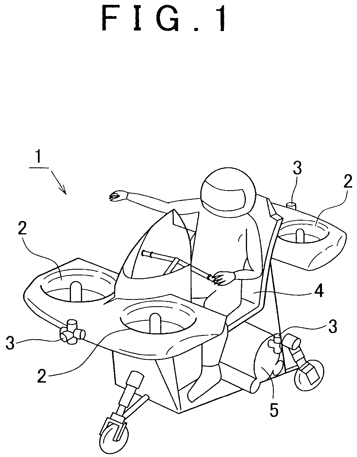
[0035]Hereafter, a first embodiment of the invention will be described. FIG. 1 illustrates the appearance of an aircraft 1 according to the example embodiments of the invention. As shown in FIG. 1, the aircraft 1 includes two thrust generators (thrust generating means) 2, which are provided at the front and rear of the aircraft 1, respectively; four reaction jet nozzles (hereinafter, simply referred to as “nozzles”) 3, which are provided at the front and rear, and on the right and left of the aircraft 1, respectively. The aircraft 1 also includes a drive source 5 provided below an occupant seat 4.

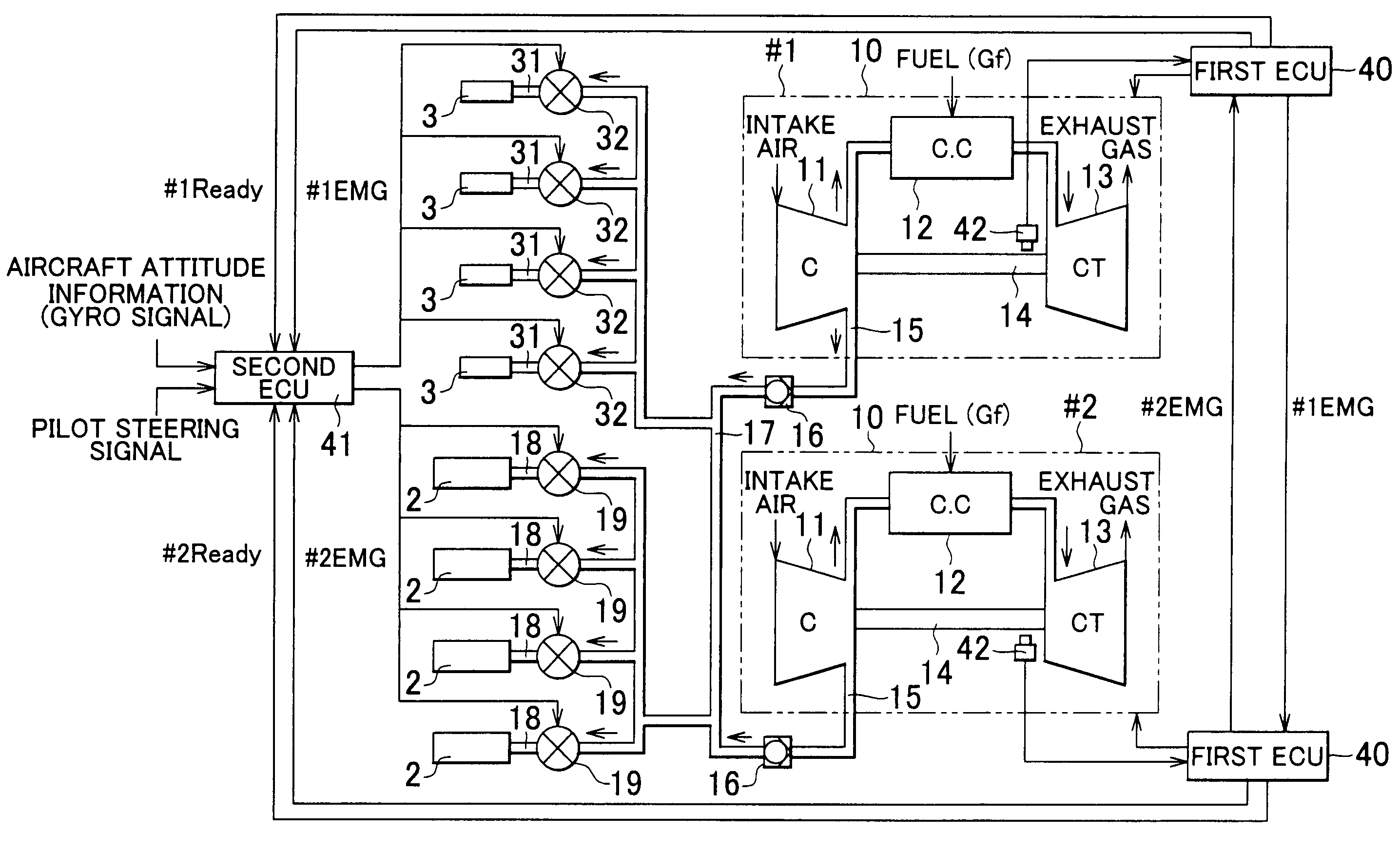
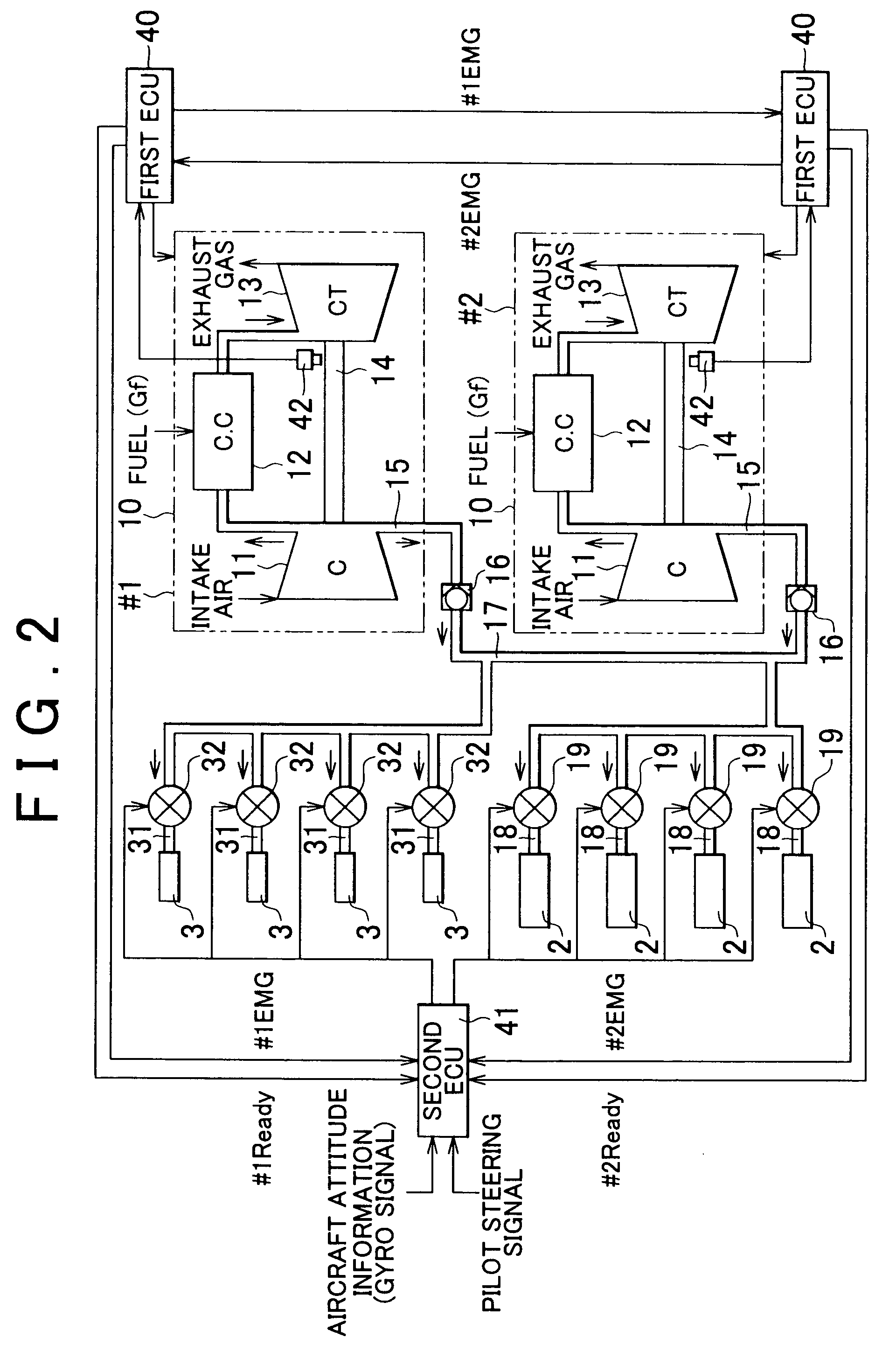
[0036]FIG. 2 schematically illustrates the configuration of the drive source 5. The drive source 5 ...


PUM


Abstract

When both engines operate properly, a control apparatus for an aircraft performs control of thrust and attitude of an aircraft using an output that is produced evenly by the two engines. When a failure occurs in one of the two engines, the control apparatus performs the control of thrust and attitude of the aircraft by increasing an output of the remaining engine that operates properly to an emergency output. When the failure occurs in one of the two engines, the control apparatus makes an engine output that is used for the control of thrust and attitude of the aircraft lower than an engine output that is used when both engines operate properly, until the remaining engine that operates properly is enabled to produce the emergency output.

Description

INCORPORATION BY REFERENCE[0001]The disclosure of Japanese Patent Application No. 2005-206002 filed on Jul. 14, 2005 including the specification, drawings and abstract is incorporated herein by reference in its entirety.BACKGROUND OF THE INVENTION[0002]1. Field of the Invention[0003]The invention relates to a control apparatus and method for controlling thrust and attitude of an aircraft provided with two gas-turbine engines.[0004]2. Description of the Related Art[0005]Published Japanese Translation of PCT application JP-T-08-502805 describes a technology related to a helicopter provided with two free turbine engines. According to the technology, when a failure is detected in one of the two engines, the upper limit of operable range for the remaining engine is increased.[0006]Aircraft, such as a helicopter, that obtains thrust using two engines are configured to ensure safe operation even in the event of an engine failure. Even if a failure occurs in one of the two engines, the airc...

Claims


Application Information

Patent Timeline
Patent Type & Authority Patents(United States)
IPC IPC(8): G05D1/08
CPCG05D1/0072
Inventor FUKUDA, DAIKI
Owner TOYOTA JIDOSHA KK
Why Eureka
Try Eureka