
Method and control device for determination of the position of a local coil in a magnetic resonance apparatus

a technology of magnetic resonance apparatus and control device, which is applied in the direction of diagnostic recording/measuring, instruments using reradiation, etc., can solve the problem of not having special measurement implemented for position determination, and achieve the effect of localization relatively safe, fast and cost-effectiv

Inactive Publication Date: 2009-10-06
SIEMENS HEALTHCARE GMBH
View PDF25 Cites 16 Cited by
  • Summary
  • Abstract
  • Description
  • Claims
  • Application Information

AI Technical Summary

Benefits of technology

[0009]An object of the present invention is to provide a fast and cost-effective method for automatic detection of the position of a local coil in which the local coil can be localized relatively safely and precisely, independent of its position on the bed, and wherein the aforementioned problems are avoided. Moreover, it is an object of the invention to specify a corresponding control device, a magnetic resonance system and a computer program product that enable the implementation of such a measurement.
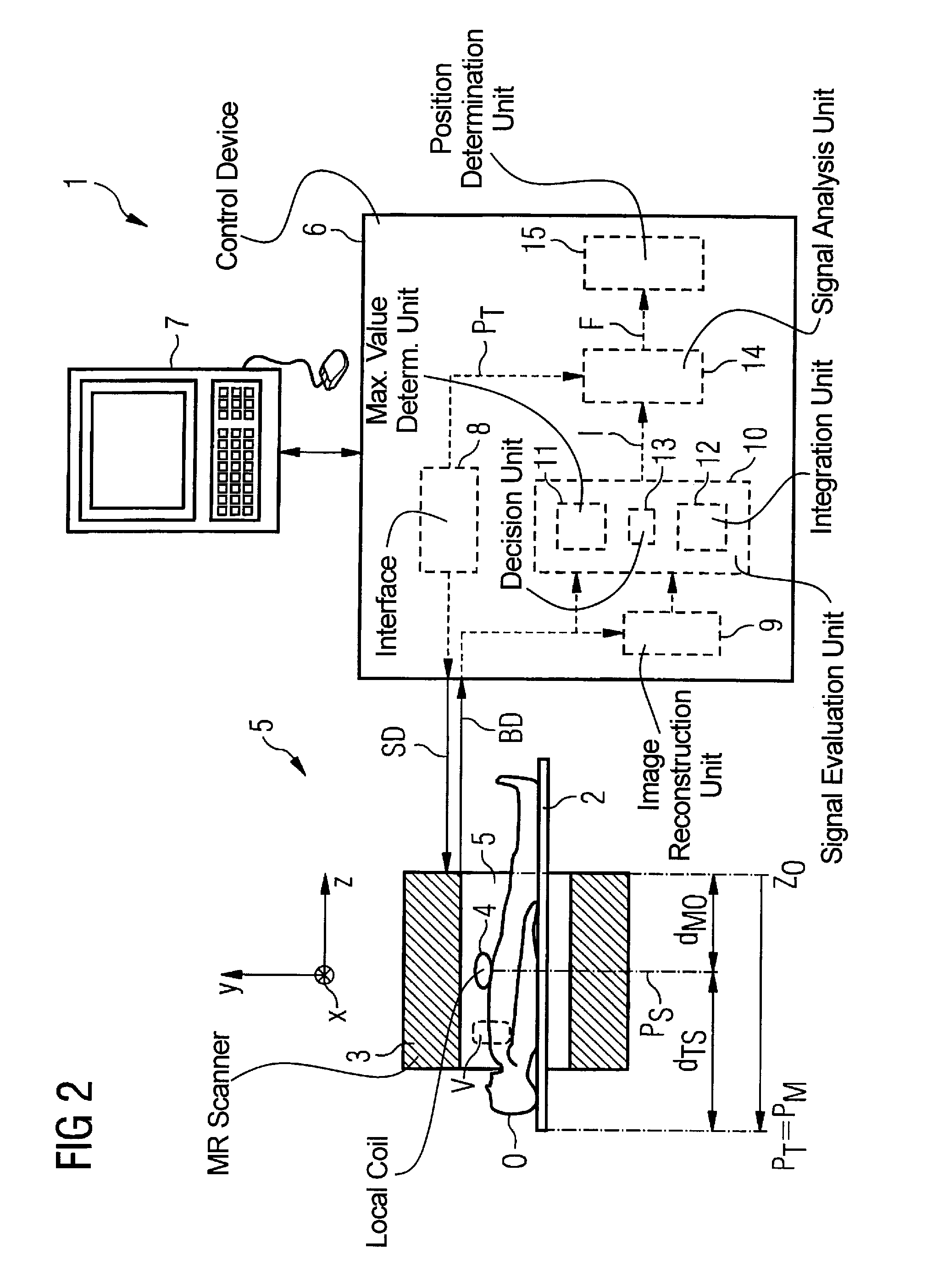
[0014]Due to the type of the method, a very reliable detection of whether a coil is located inside or outside of the scanner (meaning inside or outside of the magnetic field developed by the magnet in the scanner) is additionally possible.
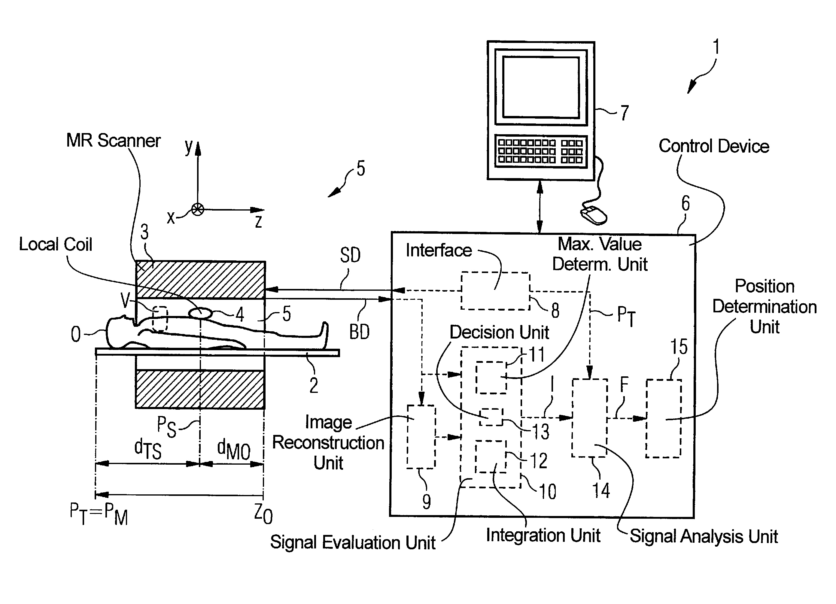
[0030]The components required for implementation of the invention in a magnetic resonance system, such as the signal evaluation unit with the maximum value determination unit, the integration unit and the decision unit as well as the signal analysis unit and the position calculation unit, can be realized completely or in a predominant part in the form of software components. Typical magnetic resonance systems have programmable control devices anyway, such that the invention is preferably realized in this manner by suitable control software. This means that a corresponding computer program product (computer-readable medium encoded with a data structure) is directly loaded into the processor of a programmable control device of the appertaining magnetic resonance system, the computer program product comprising program code in order to implement the inventive method. Existing control devices or magnetic resonance systems thus can easily be retrofitted (upgraded) for implementation of the inventive method.

Problems solved by technology

This means that no special measurement is implemented for the position determination.

Method used


Image

  • Method and control device for determination of the position of a local coil in a magnetic resonance apparatus
  • Method and control device for determination of the position of a local coil in a magnetic resonance apparatus
  • Method and control device for determination of the position of a local coil in a magnetic resonance apparatus

Examples


Embodiment Construction

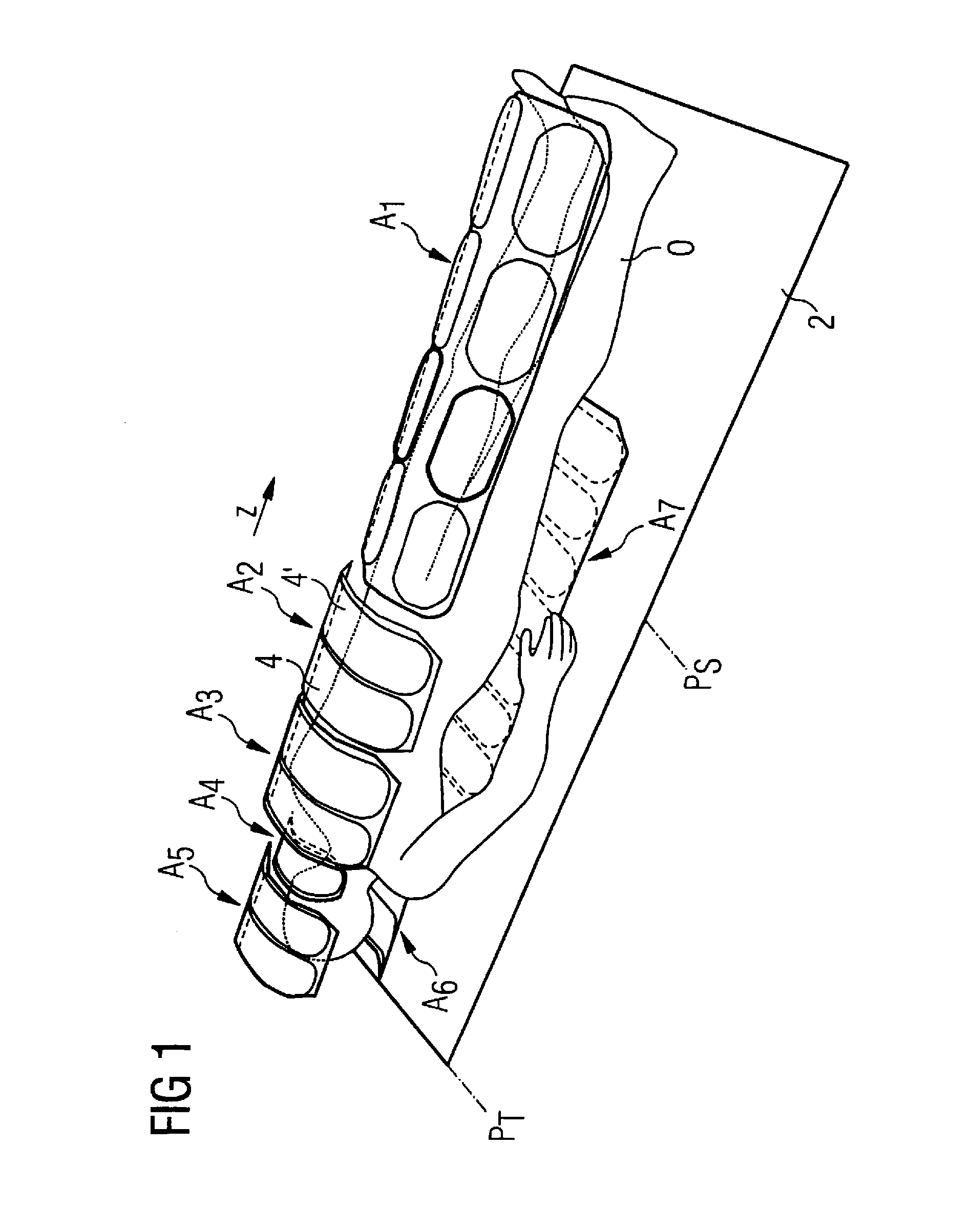
[0036]FIG. 1 schematically shows a typical examination situation in which a patient O (or, respectively, a test subject) lies on a bed 2 and a number of local coil arrays A1, A2, A3, A4, A5, A6, A7 are positioned both under the patient O and on the patient O. Such a local coil array A1, A2, A3, A4, A5, A6, A7 normally has a number of individual local coils. In the shown case, a large array A7 with eight individual coils lies below the patient O in the spinal column region up to the knee region. Two arrays A5, A6 with two coils respectively lie below the head and on the face of the patient O, with which two arrays A5, A6 images of the head of the patient O are acquired. A further array A4 (here only one coil) is placed on the neck of the patient O. Two arrays A2, A3 with respectively two larger local coils are furthermore located on the chest area and abdomen area of the patient O. A local coil array A1 with eight local coils in total is placed on the legs of the patient O.

[0037]For ...


PUM


Abstract

In a method for determination of a position of a local coil on a bed in at least one spatial direction within a magnetic resonance scanner, a signal intensity value is initially, extracted from magnetic resonance measurements implemented with the appertaining local coil for acquisition of magnetic resonance images of an examination subject and / or for measurement of further system parameters at each of various positions of the recumbent bed relative to the tomograph. The functional dependency of the extracted signal intensity values on the position of the bed relative to the scanner is then determined. The position of the local coil on the bed is determined on the basis of the determined functional dependency. A corresponding control device for a magnetic resonance system and a computer program product implement the method.

Description

BACKGROUND OF THE INVENTION[0001]1. Field of the Invention[0002]The invention concerns a method for determination of the position of a local coil on a patient bed in at least one spatial direction within a magnetic resonance tomograph apparatus. The invention moreover concerns a corresponding control device for a magnetic resonance system for determination of the position of a local coil in a scanner of a magnetic resonance system that implements such a method, a magnetic resonance system with such a control device as well as a corresponding computer program product that can be directly loaded into a processor of a programmable control device of a magnetic resonance system in order to implement such a method.[0003]2. Description of the Prior Art[0004]Modern magnetic resonance system normally operate with a number of various RF antennas (called coils in the following) for emission of radio-frequency pulses for exciting nuclei so as to emit magnetic resonance signals and / or for acquis...

Claims


Application Information

Patent Timeline
Patent Type & Authority Patents(United States)
IPC IPC(8): G01V3/00A61B5/055
CPCG01R33/3415A61B5/055
Inventor CAMPAGNA, SWEN
Owner SIEMENS HEALTHCARE GMBH
Learn More