Automated bypass method and apparatus

a bypass system and automatic technology, applied in the direction of air-break switches, emergency power supply arrangements, relays, etc., can solve the problems of difficult to determine the operation of the bypass system, little or no intuitive information, and early bypass systems that were hardware intensive, so as to improve the cost and reduce the current passing/breaking capability

Active Publication Date: 2009-10-06
SIEMENS IND INC
View PDF2 Cites 11 Cited by
  • Summary
  • Abstract
  • Description
  • Claims
  • Application Information

AI Technical Summary

Benefits of technology

[0008]The present invention addresses at least some of the above needs, and in certain embodiments addresses many of the above needs, in an arrangement for providing alternate sources of energy to an electrical device, the arrangement displaying different configurations of indicators representative of different states of operation of the arrangement, and at least another configuration of indicators representative of a condition in which the arrangement is between active states. Other embodiments improve cost by implementing an arrangement in which an inverter is deactivated before the inverter is disconnected from the load. By deactivating the inverter first, the contacts of the switch that disconnects the inverter would require less current passing / breaking capability.

Problems solved by technology

Early bypass systems were hardware intensive, and provided little or no intuitive information as to their operation to an observer.
Because of the lack of information, it could be difficult determining how the bypass system was operating, much less why the system was in a particular state or mode.
Moreover, the electrical circuits of the early bypass systems required a relatively large number of assembled parts and provided limited functionality.

Method used


Image

  • Automated bypass method and apparatus
  • Automated bypass method and apparatus
  • Automated bypass method and apparatus

Examples


Embodiment Construction

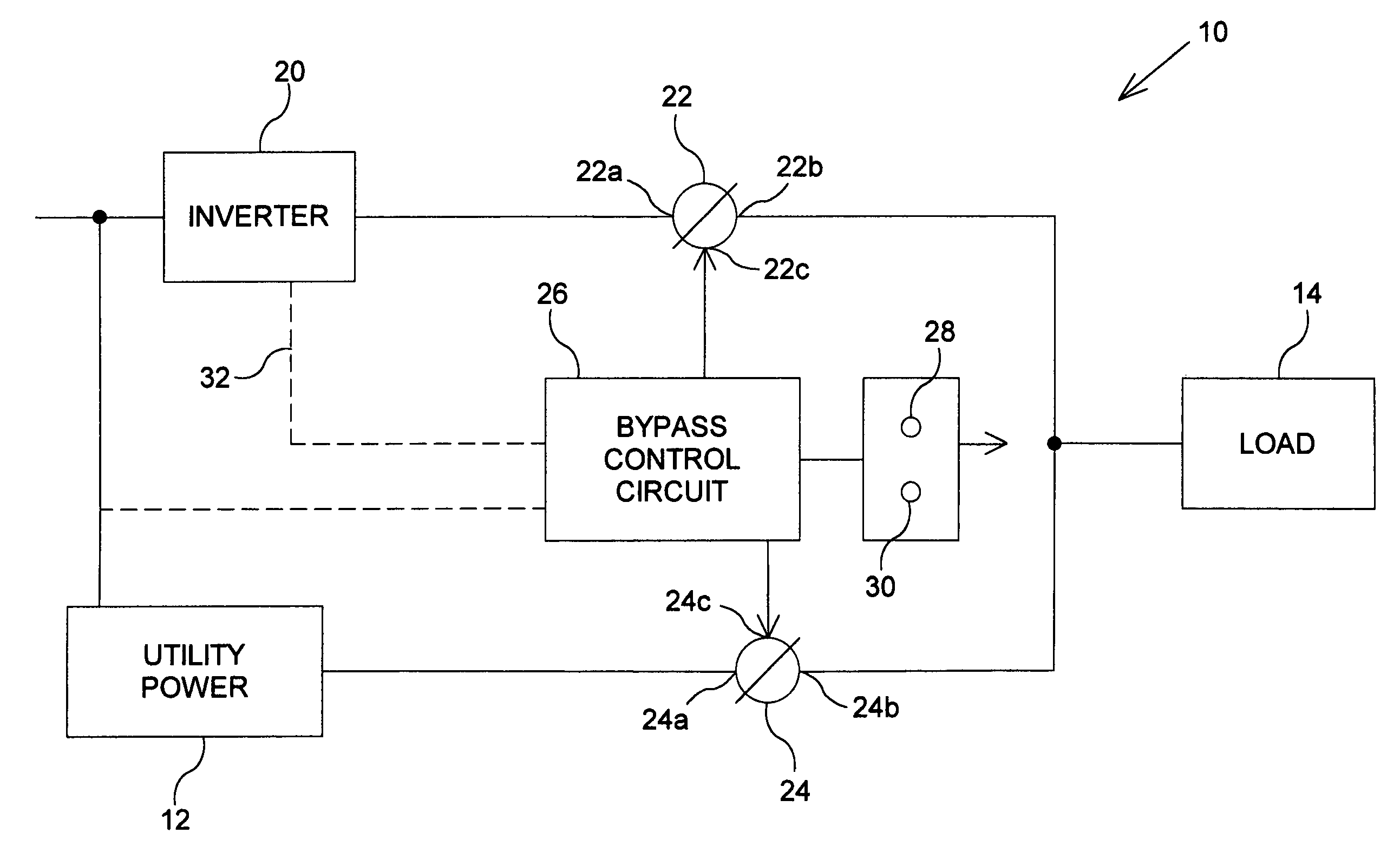
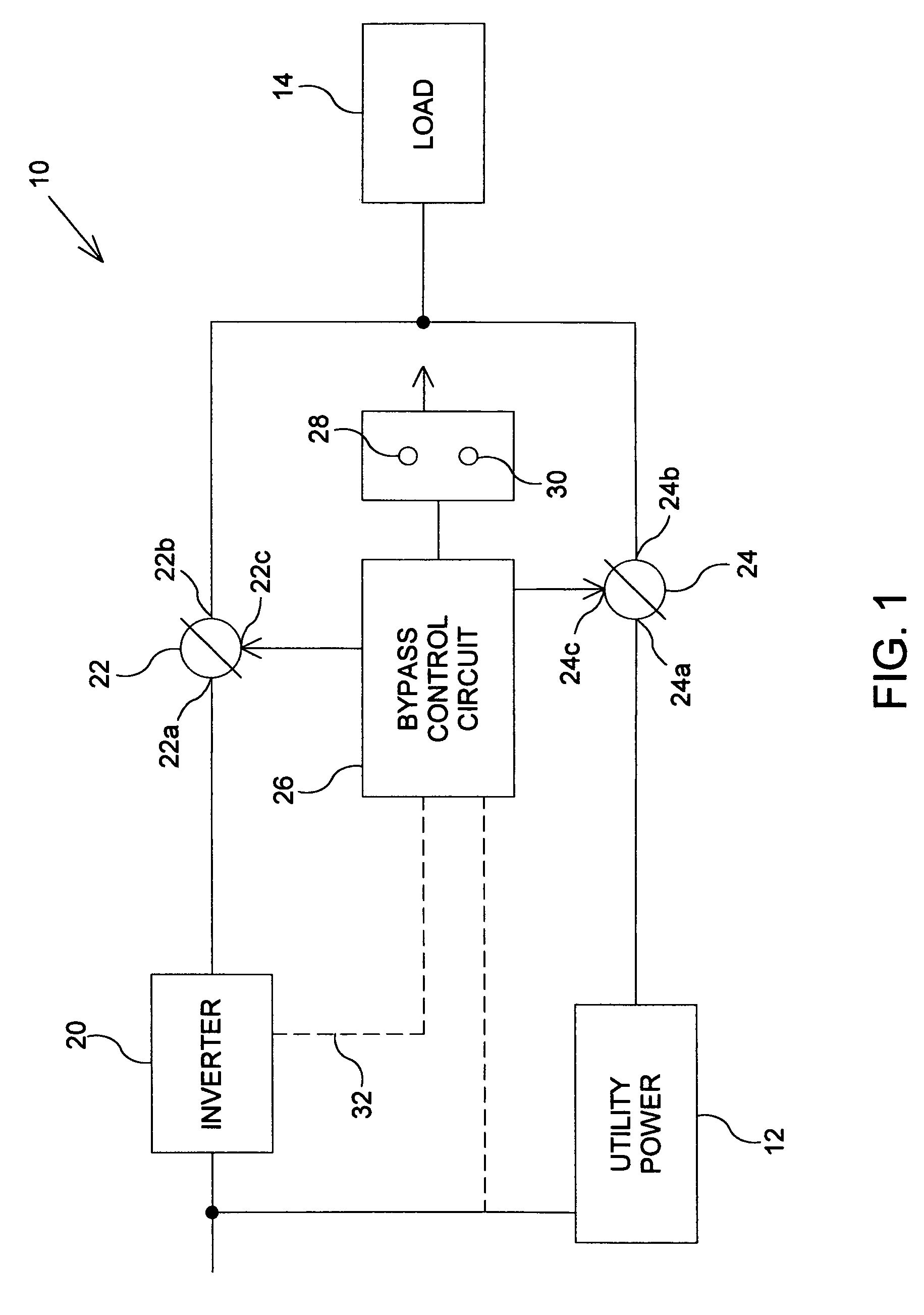
[0019]FIG. 1 illustrates an exemplary arrangement 10 for providing alternative sources of power to a load according to aspects of the invention. The arrangement 10 is shown in context with a source of utility power 12 and a load 14. The arrangement 10 includes an inverter 20, a first switch 22, a second switch 24, a bypass control circuit 26, and first and second indicators 28 and 30, respectively. In general, the arrangement 10 selectively provides a connection between utility power 12 and the load 14 in some circumstances and provides a connection between the inverter 20 and the load 14 in other circumstances. The arrangement 10 also provides information regarding the current condition of the elements of the arrangement 10 using the first and second indicators 28 and 30.

[0020]By way of example, the load 14 may be a synchronous AC machine that operates in conjunction with the frequency of the AC input power signal. While the load 14 may operate from the AC power from the utility po...


PUM


Abstract

An arrangement that provides power to an electrical device includes an inverter, first and second switches, and a bypass controller. The first switch has open and closed positions, and is operable to connect the inverter to the electrical device when in the closed position. The second switch has open and closed positions, and is operable to connect a utility power line source to the electrical device when in the closed position. The bypass controller is operable to cause a transition sequence in which the first switch changes to the open position and the second switch changes to the closed position. The bypass controller is further operable to: cause continuous actuation of a first indicator when the first switch is closed; cause continuous actuation of a second indicator when the second switch is closed; and cause intermittent actuation of the second indicator during at least part of the transition sequence.

Description

[0001]This application claims the benefit of U.S. Provisional Patent Application Ser. No. 60 / 435,107, filed Dec. 20, 2002, which is incorporated herein by reference.FIELD OF THE INVENTION[0002]The present invention relates generally to systems that provide power to electrical equipment, and more particularly, to systems that provide electrical power from multiple alternative sources to electrical equipment.BACKGROUND OF THE INVENTION[0003]Certain types of electrical equipment, for example, motors and other devices, can be configured to receive electrical power from multiple alternate sources. One common configuration is an AC motor that is powered by either the utility AC power lines, or by a variable frequency drive. In common applications, the variable frequency drive is used as a primary source of electrical power because it can be used to vary the speed of an AC synchronous motor. However, utility AC power is provided as a back-up in the event that the variable frequency drive h...

Claims


Application Information

Patent Timeline
Patent Type & Authority Patents(United States)
IPC IPC(8): H01H33/59H01H47/00H02J9/06
CPCH02J9/062H02J2009/068H02J9/068
Inventor ZVER, RONALDSMITH, EDWARDCHARLES, DONALD
Owner SIEMENS IND INC
Why Eureka
Try Eureka