
Oxygen-chemical agent sensor

a technology of gas sensor and chemical agent, which is applied in the direction of liquid/fluent solid measurement, material electrochemical variables, instruments, etc., can solve the problems of less sensitivity of electrochemical sensors with solid electrolytes, less sensitivity of electrochemical sensors, and inability to sensing oxygen in aircraft engines. achieve the effect of enhancing the resistive effect and greater sensitivity

Inactive Publication Date: 2009-10-06
APPLIED NANOTECH HLDG
View PDF5 Cites 17 Cited by
  • Summary
  • Abstract
  • Description
  • Claims
  • Application Information

AI Technical Summary

Benefits of technology

The sensor achieves high sensitivity and selectivity, enabling detection of trace amounts of gases down to parts-per-billion, including oxygen in fuel tanks and nerve agents, with improved resistance changes and reduced interference from fuel vapors, making it suitable for combustion control and safety applications.

Problems solved by technology

The electrochemical sensors which are popular fail in sensing oxygen in aircraft engines, due to the lack of accuracy and contaminants from interfering fuel vapors.
The “wet” electrochemical sensor has inherent disadvantages of leakage and the “dry” electrochemical sensors with solid electrolytes (e.g., cationic and anionic membranes, xerogels) have lesser sensitivity and are influenced by humidity and temperature.
The sensor should have low maintenance, high reliability, low cost and reasonable recovery times. The normal electrochemical sensors attractive for the detection of various gases are not suitable for this application, due to the possible contamination of the electrolyte with the fuel vapors.
Present-day conductometric sensors cannot distinguish between different electron donating or electron accepting species.
This leads to cross-sensitivity or interference between the different gaseous species.

Method used


Image

  • Oxygen-chemical agent sensor
  • Oxygen-chemical agent sensor
  • Oxygen-chemical agent sensor

Examples


Embodiment Construction

[0025]In the following description, numerous specific details are set forth such as specific substrate materials to provide a thorough understanding of the present invention. However, it will be obvious to those skilled in the art that the present invention may be practiced without such specific details. In other instances, well known circuits have been shown in block diagram form in order not to obscure the present invention in unnecessary detail. For the most part, details concerning timing considerations and the like have been omitted inasmuch as such details are not necessary to obtain a complete understanding of the present invention and are within the skills of persons of ordinary skill in the relevant art.

[0026]Refer now to the drawings wherein depicted elements are not necessarily shown to scale and wherein like or similar elements are designated by the same reference numeral through the several views.

[0027]Carbon nanotubes (CNTs) are extremely oxygen sensitive, and that oxy...


PUM

PropertyMeasurementUnit
electrophilicaaaaaaaaaa
semiconductingaaaaaaaaaa
n-type semiconductoraaaaaaaaaa

Abstract

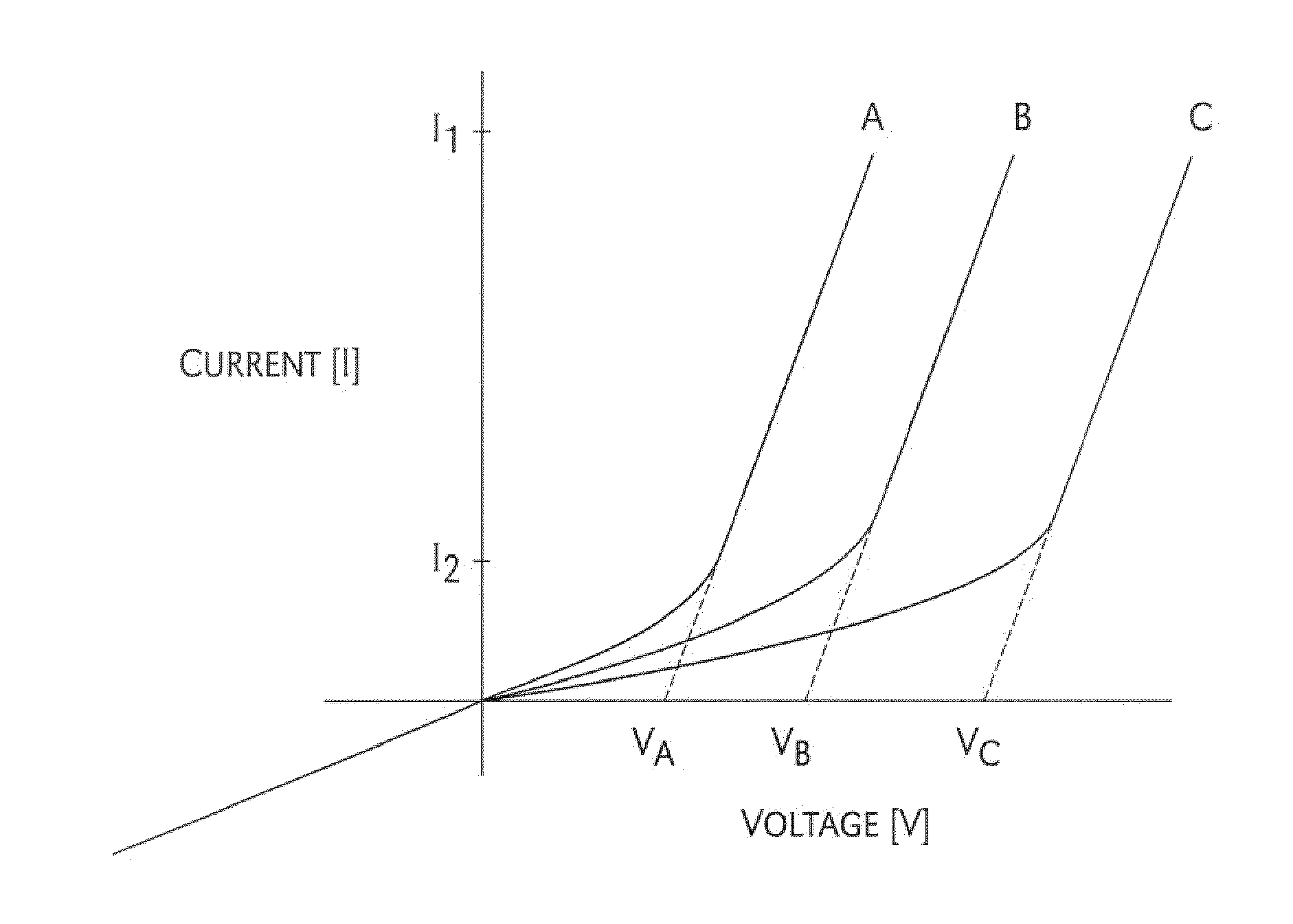
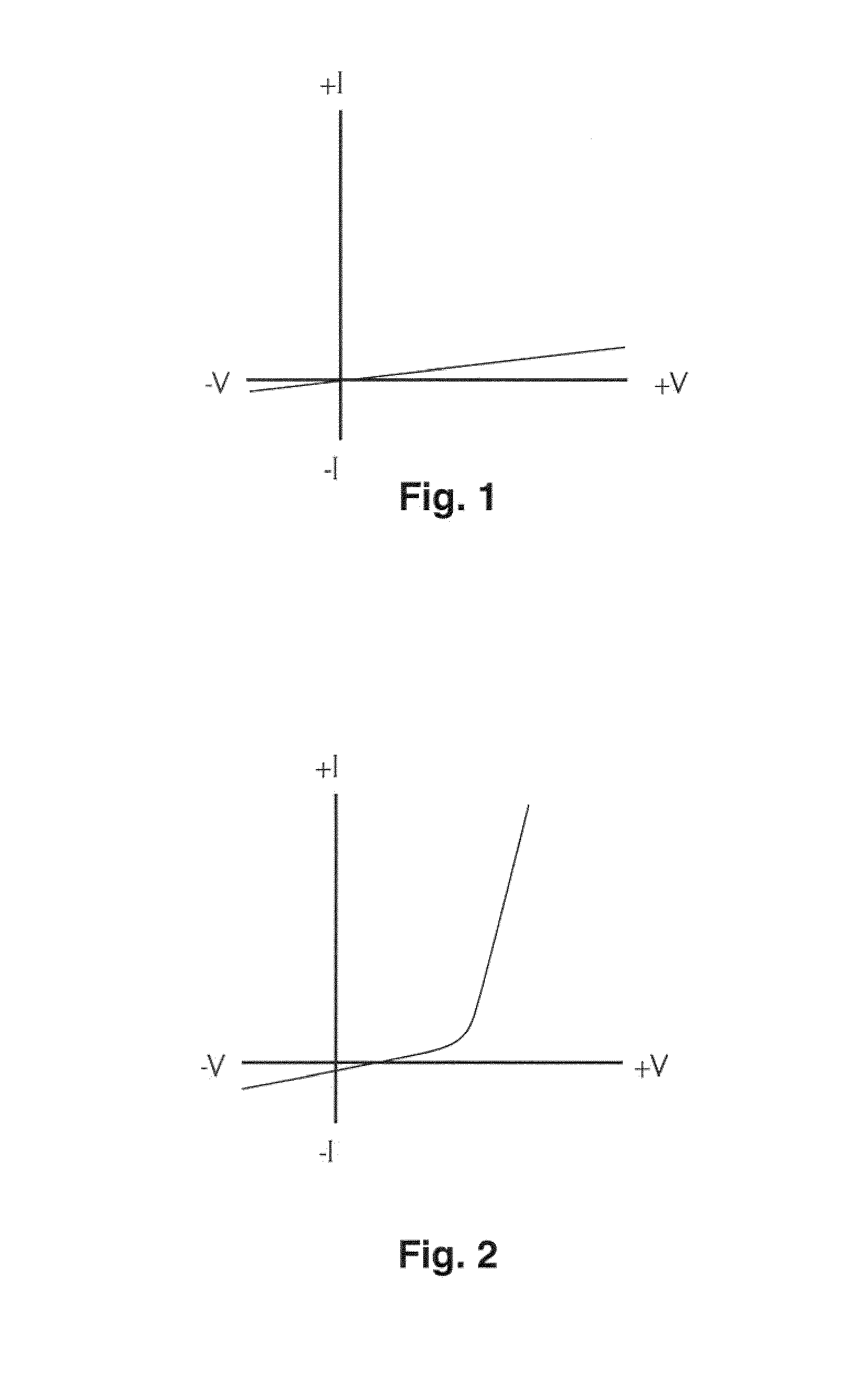
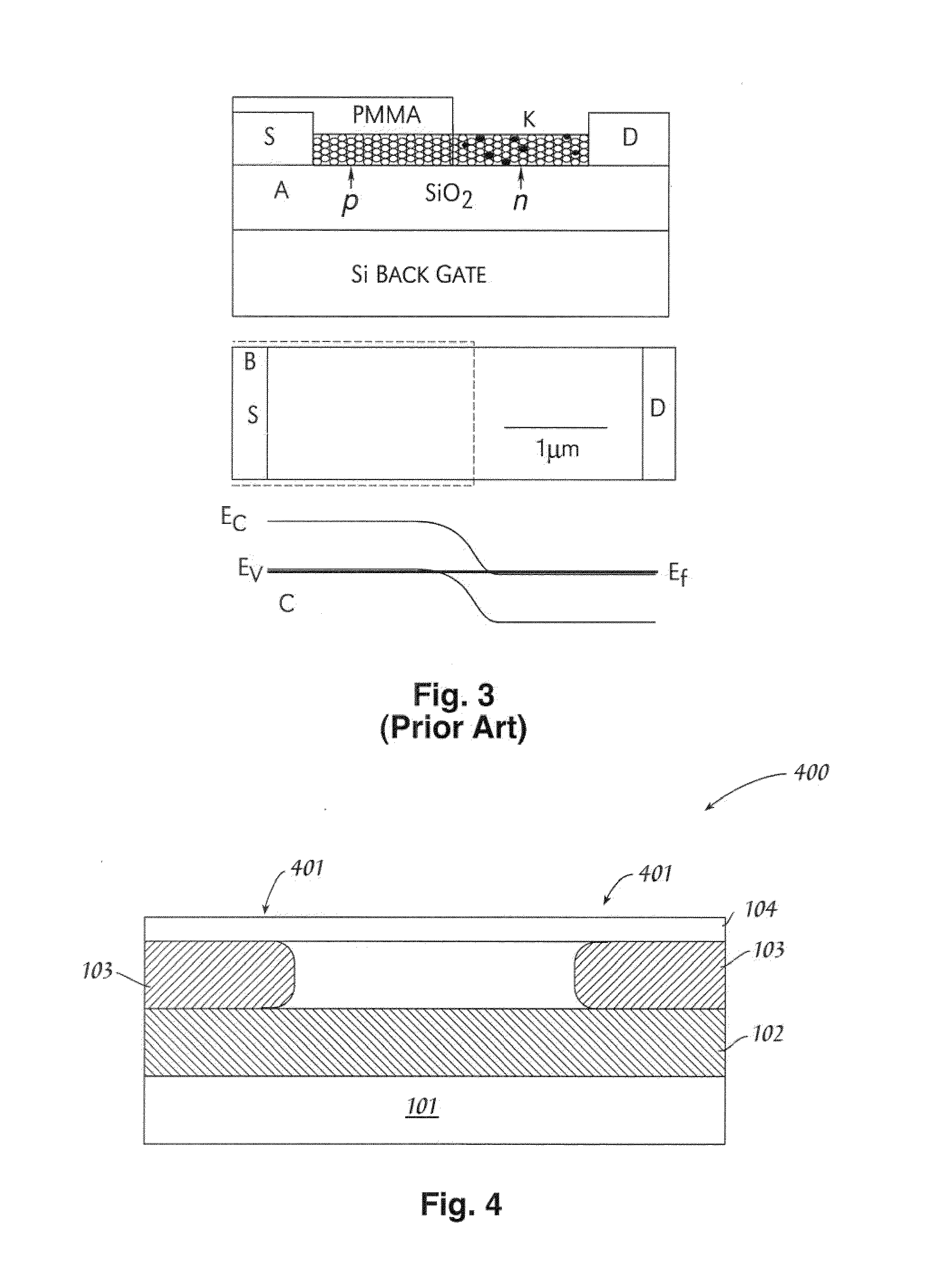
A gas sensing mechanism and a gas sensor based on a semiconducting carbon nanotube diode structure are disclosed. The gas sensor operates by detecting the change in conductivity characteristic of the current vs. voltage behavior of an I—N, or I—P junction, in the carbon nanotube. In the presence of electrophilic gas species at the I—N junction, or nucleophilic gas species at the I—P junction, a P—N, or N—P, junction is created by doping of the carbon nanotube by the respective gas species. The resulting change from the undoped, instrinsic i-type to p-type, or n-type, creates a diode structure whose conductivity characteristics can be measured with high accuracy and selectivity.

Description

CROSS-REFERENCE TO RELATED APPLICATIONS[0001]The present invention claims priority under 35 U.S.C. §119(e) to U.S. Provisional Patent Application Ser. No. 60 / 589,408 filed Jul. 20, 2004.TECHNICAL FIELD[0002]The present invention relates in general to gas sensors, and in particular to oxygen and chemical agent gas sensors using carbon nanotube cathodes.BACKGROUND INFORMATION[0003]Most of the present-day gas sensors based on carbon nanotubes are conductometric, that is, a response of the sensor based on the resistance change due to contact with the gas. That change is usually due to a doping process.[0004]The electrochemical sensors which are popular fail in sensing oxygen in aircraft engines, due to the lack of accuracy and contaminants from interfering fuel vapors. The “wet” electrochemical sensor has inherent disadvantages of leakage and the “dry” electrochemical sensors with solid electrolytes (e.g., cationic and anionic membranes, xerogels) have lesser sensitivity and are influen...

Claims


Application Information

Patent Timeline
Patent Type & Authority Patents(United States)
IPC IPC(8): G01N27/403
CPCB82Y15/00G01N27/127B82Y30/00Y10S977/957
Inventor VISEL, THOMASSOUNDARRAJAN, PRABHU
Owner APPLIED NANOTECH HLDG
Learn More