
Ultra low flow spray head

a spray head and ultra-low flow technology, applied in the direction of burners, combustion types, combustion processes, etc., can solve the problems of polluting other areas, affecting the geology, topography and composition of soils, and affecting the actual resource of water

Active Publication Date: 2009-10-06
AQUARIUS BRANDS +1
View PDF27 Cites 20 Cited by
  • Summary
  • Abstract
  • Description
  • Claims
  • Application Information

AI Technical Summary

Benefits of technology

"The patent is about a new invention of a spray head for low-volume irrigation, which is used in agricultural and horticultural applications. The spray head is designed to deliver water to plants at a rate of ½ gallon per hour, which is much lower than the traditional spray heads that can deliver more than 2 gallons per hour. This invention helps to conserve water and soil, as well as improve plant health and crop yields. The patent also discusses the importance of topography and climate in designing these low-volume irrigation systems, as well as the need for intermittent watering to prevent soil erosion and pollution. The patent also mentions previous art related to low-volume irrigation devices and the limitations of these devices in terms of flow rate and tolerance of manufacturing variables. The new spray head invention offers a solution to these limitations and provides a more efficient and effective tool for low-volume irrigation."

Problems solved by technology

Conventional watering systems, such as hose end devices and conventional lawn sprinklers and bubblers, can deliver more than 125 gallons per hour, causing much waste not only of the actual resource of the water but alters the geology, topography and composition of the soils.
Excess water usually runs away from the planting area causing erosion, which carries off the valuable top soil and causes damage to the plants as their roots can become exposed and dry out.
Runoff water can also carry with it fertilizers and soil nutrients, which can pollute other areas and rob the plant of its food source.
Excess watering also causes the leeching of dissolved salts and minerals from the ground and concentrates them where the runoff is collected, often killing whatever vegetation is present due to the high concentrations of salt and heavy metals.
Excess water also creates an economic disadvantage as there exist the actual cost of the wasted water and the cost of the power to pump the water from it's source.
Hillside applications, especially in the grape growing and citrus growing regions where good land is very valuable and is often not flat, present problems.
Point source devices will deliver water only to a specific point limiting coverage and creating runoff as gravity pulls the water away from the plant and may not be able to deliver a sufficient amount of water, and sprinklers will deliver too much water and will cause the erosion effects described supra.
Windy conditions also affect micro irrigation when sprinklers and sprayers are used.
Due to the size of the droplet produced, which is much smaller than a conventional sprinkler due to the decreased volume of water, wind will blow the spray away from the intended watering area.
Point source devices are not susceptible to this wind, but may not be able to deliver a sufficient amount of water and will not be able to do so over a wetted area.
Unfortunately, for this device to function in the range of ½ gallon per hour, the tolerance of manufacturing variables in the many pieces present would be impractical for high volume manufacturing.
Also this device would not be able to able to internally cleanse itself as there are many internal corners and narrow passageways where dirt and dissolved solids would accumulate and cause failure.
Also due to the friction created by the many turns the water must go through, there is a substantial pressure drop.
These devices however reduce the amount of flow while also reducing the pressure through friction as well, so that the resulting flow is delivered at a de minims amount of pressure.
Due to this low pressure and the small openings of the labyrinth, these devices are often prone to clogging through particle and mineral deposits.
These devices function well at higher flow volumes but are limited to those flows approximately 6 gallons per hour and above as the size of the hole necessary to create a lower flow causes problems in the manufacturability and functionality of the flow control as well as presenting issues with cleaning and clogging.
In this application, which relies on a high velocity stream of fluid, a flow control disk of correct cross-sectional orifice size would not allow for enough velocity.
By decreasing the size of the orifice, the amount of water is decreased as water is not capable of decreasing in volume as pressure is increased.
This also causes a pressure differential between the two sides of the orifice.
The restriction of nozzle size is applicable to high flow devices such as lawn sprinklers which are delivering 60-90 gallons per hour or more, but the size of the orifice required to create flows necessary for low volume irrigation is very small.
An orifice this small will easily be obstructed by the dissolved solids and impurities present in the water, as filtration would generally not be able to remove such small particles.
Also after the water is turned off, calcium and other hard minerals are left on the surface of the orifice through evaporation, clogging the nozzle prior to the next operation.
Unfortunately, for these devices to be able to eject large volumes of water, there orifice size must be larger and that invites insects to enter and block the passages.
Also due to the need to develop the casing, these products are difficult to manufacture and expensive.
This device as designed will not function completely at low flow rates, and due to the narrow size of the passages required for low flow rate, this device is prone to failure with the accumulation of dissolved solids in the water and requires a complex disassembly to clean the device.
This self-cleaning action is desirable as filtration in large field applications are not capable of trapping such small sediment that would otherwise clog static devices.
It would be advantageous to have very low volumes of water to be sprayed over a small wetted area, and the current devices are not capable of performing such a need.
The prior art either decreases the flow rate by also decreasing the pressure or does not decrease the flow rate low enough with sufficient pressures.

Method used


Image

  • Ultra low flow spray head
  • Ultra low flow spray head
  • Ultra low flow spray head

Examples


Embodiment Construction

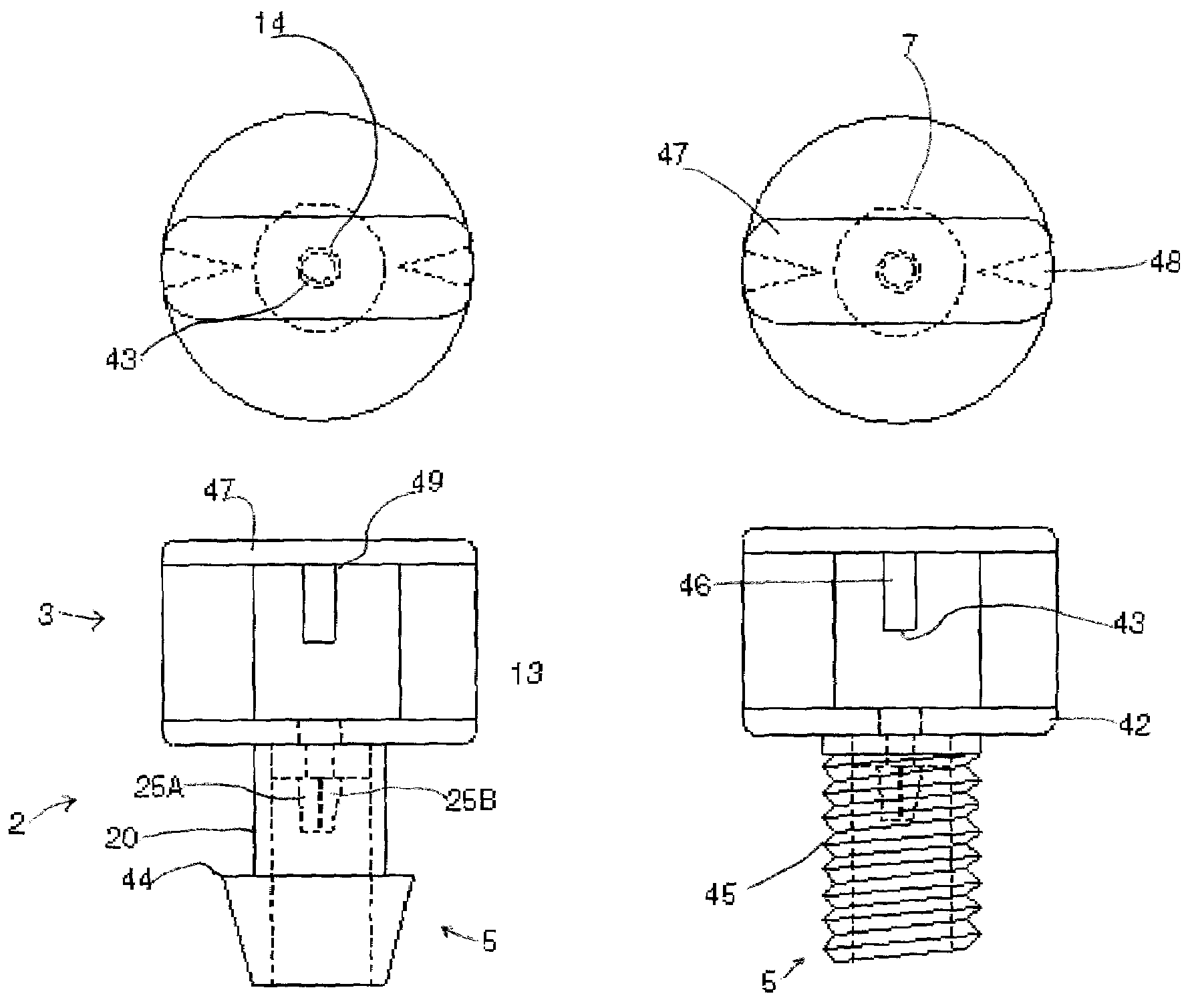
[0024]The present invention will be detailed in relation to the aforementioned drawings. All disclosure is representative of the best mode of practicing this invention but that it is assumed that those skilled in the art will be able to practice this invention in other fields of application, nor does this disclosure limit the construction of this invention to the parts herein disclosed. Applicant recognizes that development of future inventions may lead to better parts than those disclosed, but the intent of this application is to show the best available parts currently available by their fit, form and function to their exclusive use by this application.

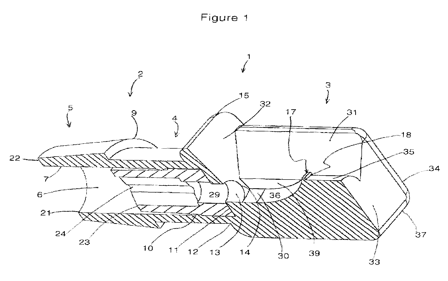
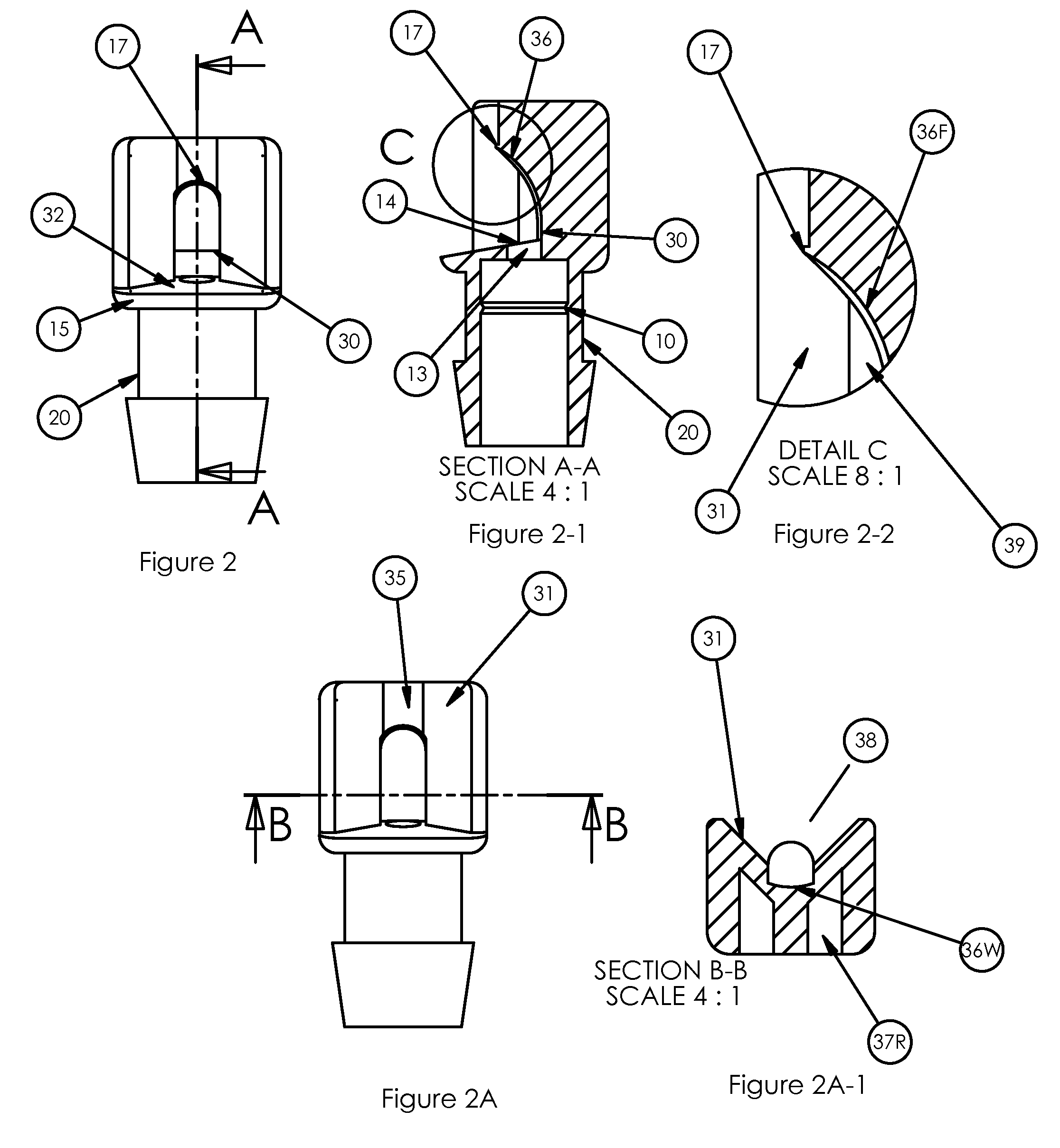
[0025]Referring to FIG. 1, whose inlet portion which is representative of the inlet sections of all style of spray heads in the present invention, Spray head 1 is shown in a cross sectional view. Head 1 is broken down into two main sections, inlet portion 2 and dispersement portion 3. Inlet 2 is the interface portion of the Head 1, w...


PUM


Abstract

An ultra low volume pressure independent spray head is disclosed whereby low flow characteristics of point source devices can be applied to larger wetted areas. Device uses elastomeric flow control where the emission channel is large enough to purge particulate matter from it's channels and the spray head has large enough orifices to allow the particulate to pass unimpeded through the discharge arena. This device is designed to utilize flow rates of less than 2 gallons per hour and can compensate for pressures between 10 and 60 pounds per square inch. Construction of this device is through the use of polymers, but other materials can be used as the design is such as to allow for a large variety of applications. This device can be used in the agricultural or horticultural application and is adapted for use in vineyards and can be used singularly or in multiple head arrangements. Design of inlet portion allows for use with flexible or rigid water supply means.

Description

CONTINUITY OF PRIOR DISCLOSURE[0001]This invention was first disclosed on May 18, 2005 through Disclosure Document Number 578357 filed with the United States Patent Office as the Ultra Low Flow Pressure Compensating Spray Head.FIELD OF THE INVENTION[0002]This invention involves the field of ultra low flow spraying devices used in the horticultural and agricultural arenas, though its application in other fields is anticipated. Ultra low flow in this application refers to fluid flows as low as ½ gallon per hour, and the preferred use of this spray head invention is between ½ gallon per hour and 2 gallons per hour.BACKGROUND OF THE INVENTION[0003]Low flow or micro irrigation is a form of irrigation of plants, row crops, trees and shrubs, where the amount of water delivered to the plant is metered into the range of ½ gallon per hour and as high as 28 gallons per hour for bubbler devices and sprayers, depending on the type of soil, type of plant or tree, and the individual requirements o...

Claims


Application Information

Patent Timeline
Patent Type & Authority Patents(United States)
IPC IPC(8): B05B1/30
CPCB05B1/3006B05B1/262
Inventor HAWKINS, STANLEY
Owner AQUARIUS BRANDS
Learn More