
Method of enhancing the external ballistics and ensuring consistent terminal ballistics of an ammunition projectile and product obtained

a technology of external ballistics and projectiles, applied in the field of small arms ammunition, can solve the problems of large displacement and/or movement (flow) of metallic jacket materials, projectiles employed in weapons desiring to impart massive destructive forces to an intended target, major deformation and/or disintegration of projectiles,

Active Publication Date: 2009-10-06
LONE STAR FUTURE WEAPONS LLC
View PDF17 Cites 4 Cited by
  • Summary
  • Abstract
  • Description
  • Claims
  • Application Information

AI Technical Summary

Benefits of technology

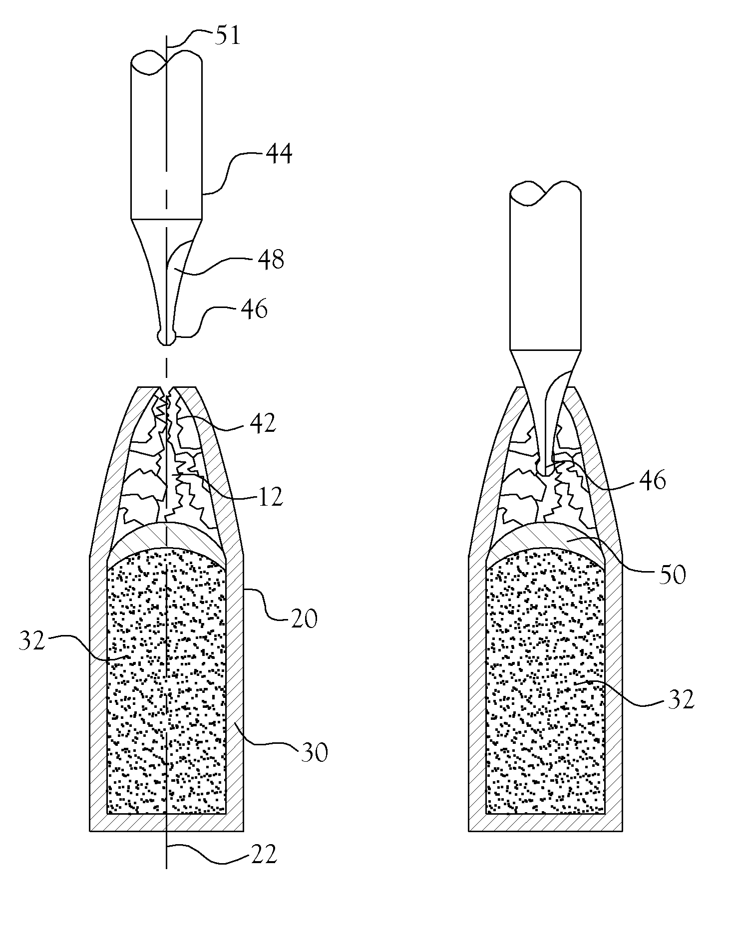
"The present invention is about improving the design of ammunition projectiles. The invention includes a flat annular face on the outermost end of the projectile's ogive portion, which is oriented perpendicular to the projectile's centerline. The invention also includes the removal of extraneous material from the projectile's meplat cavity while maintaining a void volume within the cavity that is concentric with the projectile's centerline. The invention also includes the provision of meplat cavities that are of uniform size and geometry from projectile to projectile. The flat annular face's wall thickness can also be altered. These geometrical enhancements improve the projectile's performance and accuracy."

Problems solved by technology

More specifically, in certain situations, projectiles employed in weapons desirably impart massive destructive forces to an intended target.
Such expansion occurs when the projectile strikes a target, such as an animal, and hydraulic pressure builds up within the meplat cavity, causing the ogive region of the projectile to commence deformation and / or disintegration of the projectile, such deformation and / or disintegration being propagated inwardly of the projectile along its length with resultant major deformation and / or disintegration of the projectile within the target.
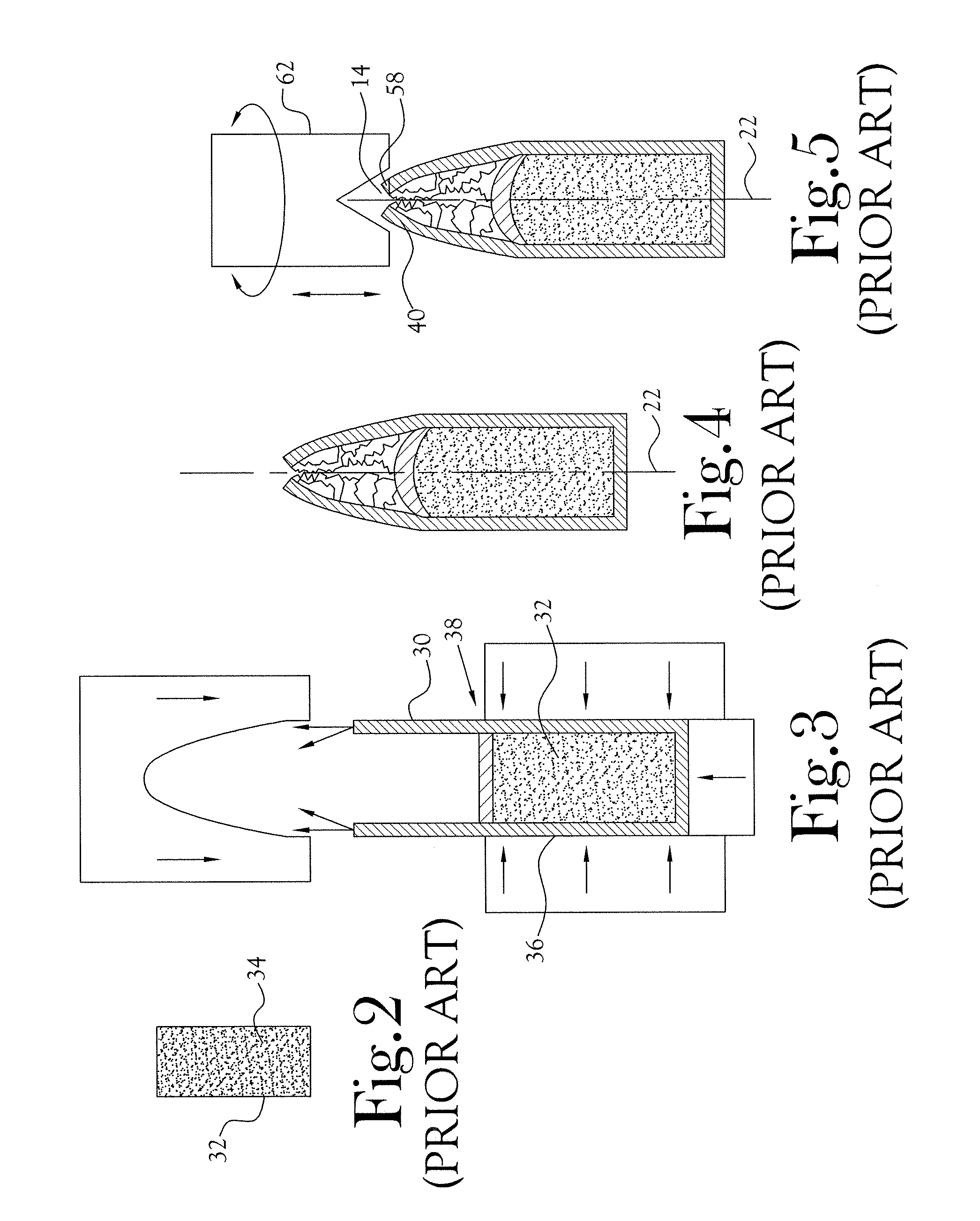
Moreover, in the process of forming an ogive on the leading end of a projectile, there occurs major displacement and / or movement (flow) of the metallic jacket material within the leading end of the jacket and in the region of the ogive.
Such action most often results in non-uniform distribution of such displaced or moved jacket material and therefore non-uniformity of the wall thickness of the jacket within the region of the ogive.
This thickness of the leading end of the jacket may increase in a direction along the ogive and away from the leading end of the jacket, Thus, when employing the prior technique of flattening the leading edge of the jacket in order to gain the selected desired overall length of the projectile, more or less of the length of the jacket is cut away, resulting in undesirable variances in wall thickness of a given projectile and also from projectile to projectile at the annular flattened face of the leading end of projectile.
Moreover, the non-uniformity of the thickness of the annular aspect of the flat face of the projectile presents a non-consistent area of impact with the ambient air mass along the circumference of the annular face.
Whereas the trimming of the leading end of the projectile to develop a consistent overall length of the projectile (and ultimately consistent uniformity of the overall length of the round of ammunition formed therefrom) reportedly serves to enhance the uniformity of flight of the projectile from the weapon barrel to the target as compared to a non-trimmed projectile, this prior art fails to fully address the uniformity of flight of the projectile and, importantly, also fails to address the issue of the terminal ballistics of the projectile when it strikes a target.

Method used


Image

  • Method of enhancing the external ballistics and ensuring consistent terminal ballistics of an ammunition projectile and product obtained
  • Method of enhancing the external ballistics and ensuring consistent terminal ballistics of an ammunition projectile and product obtained
  • Method of enhancing the external ballistics and ensuring consistent terminal ballistics of an ammunition projectile and product obtained

Examples


Embodiment Construction

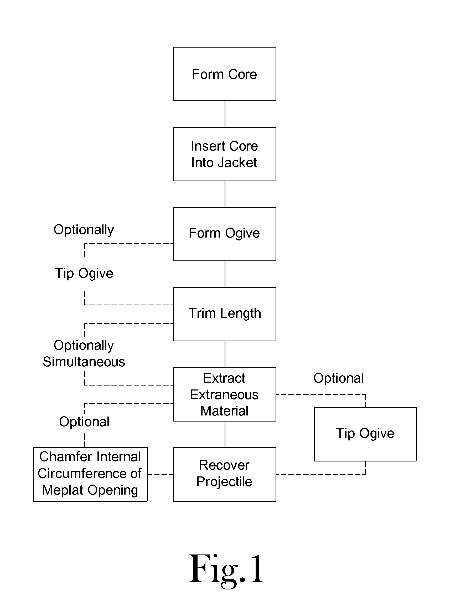
[0025]The present invention, in one aspect, (see FIG. 11), is directed to development of a meplat cavity 12 and its associated opening 14 following the formation of an ogive 16 on the leading end 18 of a projectile 20 with resultant establishment of uniformity from projectile to projectile of a plurality of projectiles of a given type, size, etc. (As used herein, “meplat” and “meplat cavity” are used synonymously unless the context of their use indicates otherwise).

[0026]In the present invention such uniformity is obtained by establishing and maintaining a meplat cavity for the projectile which (from projectile to projectile) is of uniform void volume, of uniform size and geometry, and which is substantially concentric with the longitudinal centerline 22 of the projectile. Additionally, the opening of the meplat of the projectile is geometrically enhanced to effect consistent external ballistics of the projectile from projectile to projectile. In one aspect of the present invention,...


PUM


Abstract

A method for geometrically enhancing of the flight of a projectile fired from a weapon to an intended target, including development of a flat annular face on the outermost end of the ogive portion of the projectile, such flat annular face being oriented in a plane that is substantially perpendicular to, and concentric with, the longitudinal centerline of the projectile, and further including extraction of extraneous material from the meplat cavity of the projectile while establishing at least a void volume within the meplat cavity which is substantially concentric with the longitudinal centerline of the projectile and of substantially uniform size and geometry from projectile to projectile. Geometric alteration of the wall thickness of the flat annular face also may be provided. An enhanced projectile and a round of ammunition are disclosed.

Description

CROSS-REFERENCE TO RELATED APPLICATIONS[0001]Not ApplicableSTATEMENT REGARDING FEDERALLY SPONSORED RESEARCH OR DEVELOPMENT[0002]Not ApplicableFIELD OF INVENTION[0003]This invention relates to small arms ammunition, and particularly to the establishment of a substantially uniformly sized void volume and uniform geometry of the void volume of a meplat cavity and its associated meplat opening on the leading end of an ammunition projectile useful in the manufacture of small arms ammunition, such as ammunition for weapons of 50 caliber or smaller.BACKGROUND OF THE INVENTION[0004]A basic round of small arms ammunition, particularly rifle ammunition, commonly comprises a case having a primer disposed in a closed end thereof and adapted to receive a quantity of gun powder interiorly thereof. The case includes an open end adapted to receive therein a projectile (also commonly referred to as a “bullet”). Among other things, the depth to which the projectile is inserted into the case desirably...

Claims


Application Information

Patent Timeline
Patent Type & Authority Patents(United States)
IPC IPC(8): F42B3/00
CPCF42B12/34F42B10/46
Inventor BEAL, HAROLD F.
Owner LONE STAR FUTURE WEAPONS LLC
Learn More