
Gear selection strategy for a dual clutch transmission

a dual clutch transmission and gear selection technology, applied in the direction of gearing, mechanical equipment, transportation and packaging, etc., can solve the problems of affecting the efficiency of asm transmission, affecting the efficiency of dual clutch transmission, and limited the rate at which they can dissipate excess power, so as to achieve low reverse ratio

Inactive Publication Date: 2009-10-06
FORD GLOBAL TECH LLC
View PDF17 Cites 41 Cited by
  • Summary
  • Abstract
  • Description
  • Claims
  • Application Information

AI Technical Summary

Benefits of technology

This strategy enhances fuel efficiency by reducing parasitic losses and clutch wear, enabling a larger gear span with fewer components, and allows for smooth transitions between forward and reverse gears without moving coupler sleeves, improving the overall performance and packaging of the transmission.

Problems solved by technology

Automatic transmissions for transmitting power between an input and an output, either over a continuously variable range of speed ratios or in discrete step changes among speed ratios, have associated with them several sources of parasitic losses, which adversely affect fuel economy.
These losses are associated with a torque converter, open hydraulic friction clutches and brakes, hydraulic pump, and gear meshes.
An ASM transmissions, are limited in the rate at which they can dissipate the excess power.
Dual clutch transmissions have parasitic losses only slightly higher than ASM transmissions.
First, it reduces the torque which the clutch must transmit.
The difference between adjacent gear ratios is limited by the ability to make comfortable shifts.
However, if the gear multiplication is high enough to satisfy clutch thermal considerations, it may be excessive for normal reverse driving, even at those relatively low speeds.
This would require increasing the distance between shafts due to limitations on how small the gears can be relative to the shaft diameter.
The resulting transmission would be much larger and likely would not fit into the package space available.
This is particularly troublesome if the clutches are very cold, which causes them to have high drag.

Method used


Image

  • Gear selection strategy for a dual clutch transmission
  • Gear selection strategy for a dual clutch transmission
  • Gear selection strategy for a dual clutch transmission

Examples


Embodiment Construction

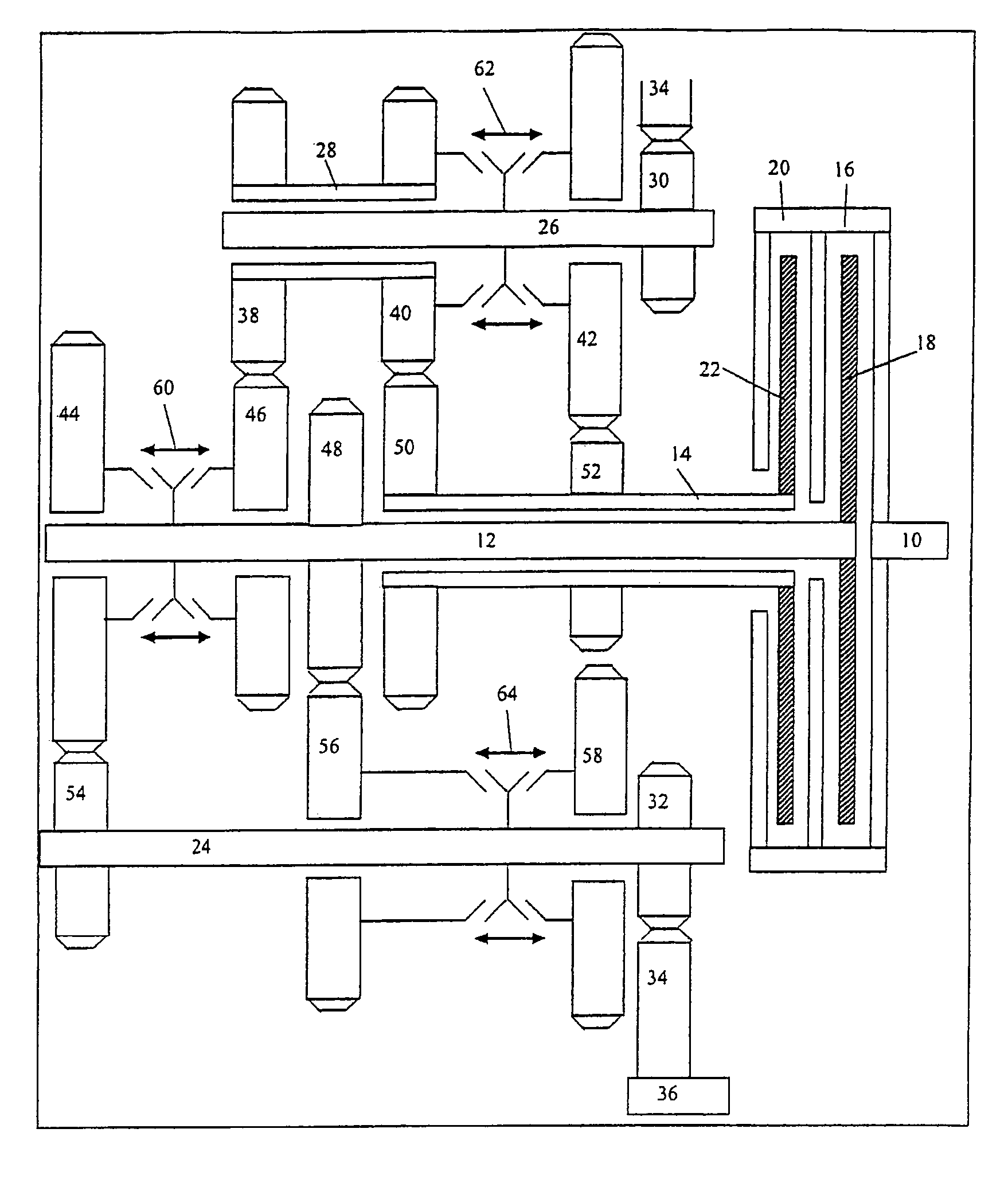
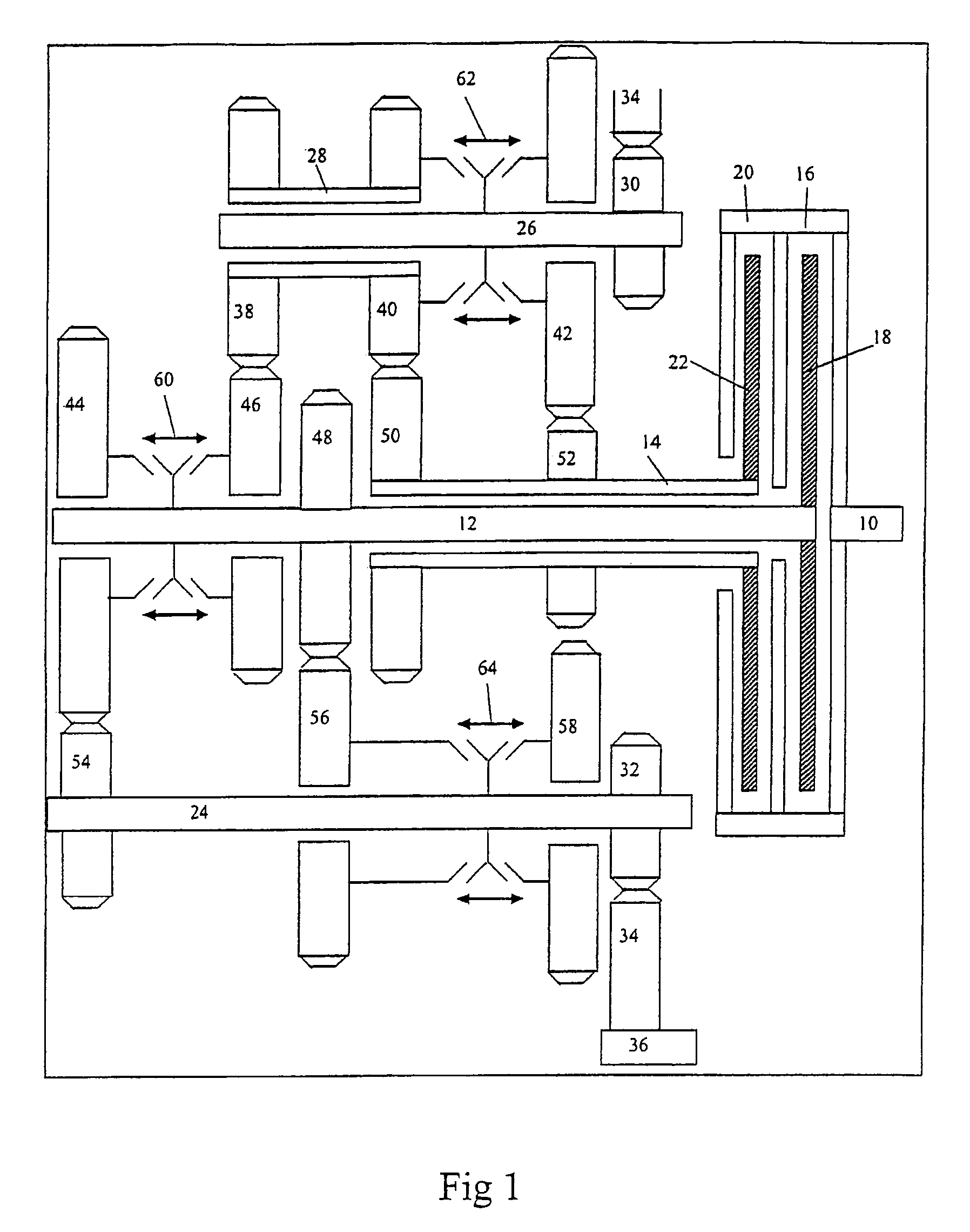
[0027]Referring to FIG. 1, a transaxle includes an input 10 for driveably connecting a power source, such as an internal combustion engine or electric motor, to the transmission, and an output 36 for driving a load, such as the driven wheels of a motor vehicle, through a powertrain that may include a drive shaft, differential mechanism, and axle shafts. A first friction clutch 20, consisting of a clutch housing and a clutch disc 22, alternately connects and disconnects a first input shaft 14 as clutch 20 is engaged and disengaged, respectively. A second friction clutch 16, consisting of a clutch housing and a clutch disc 18, connects and disconnects a second input shaft 12 as clutch 16 is engaged and disengaged, respectively.

[0028]A first layshaft 26 supports a first output pinion 30, which is secured to layshaft 26 in continuous meshing engagement with an output ring gear 34, secured to output 36. A second layshaft 24 supports a second output pinion 32, which is secured to the lays...


PUM


Abstract

A method for controlling gear shifts in a multiple speed power transmission for a vehicle that includes a first clutch for transmitting power through a first power path producing a reverse gear, and a second clutch for transmitting power through a second power path producing a forward gear. The method includes selecting a reverse range in which the transmission is to operate, preparing the transmission to transmit power alternately through the first power path and second power path; engaging the first clutch and transmitting power through the first power path in the reverse gear, selecting a forward range in which the transmission is to operate, disengaging the first clutch and engaging the second clutch, and transmitting power through the second power path in the forward gear.

Description

CROSS-REFERENCE TO RELATED APPLICATION[0001]This application is a continuation-in-part of the U.S. patent application Ser. No. 11 / 083,250, filed Mar. 17, 2005 now U.S. Pat. No. 7,246,536.BACKGROUND OF THE INVENTION[0002]Automatic transmissions for transmitting power between an input and an output, either over a continuously variable range of speed ratios or in discrete step changes among speed ratios, have associated with them several sources of parasitic losses, which adversely affect fuel economy. These losses are associated with a torque converter, open hydraulic friction clutches and brakes, hydraulic pump, and gear meshes.[0003]To improve fuel economy in a motor vehicle having an automatic transmission, an automated shift manual (ASM) transmission can be used to eliminate or substantially reduce all of these parasitic losses except gear mesh losses. An ASM transmissions, are limited in the rate at which they can dissipate the excess power. The amount transmission generally perf...

Claims


Application Information

Patent Timeline
Patent Type & Authority Patents(United States)
IPC IPC(8): F16H3/097B60W10/10B60W30/18
CPCB60W10/113F16H3/006F16H61/0246F16H61/688B60W30/18045Y10T74/1926F16H59/18F16H2003/0826F16H2003/0931F16H2003/0933F16H2200/0047F16H2200/0056F16H2200/0086F16H2306/18F16H2312/02F16H2312/08F16H2003/0807Y10T74/19251Y10T74/19228Y10T74/19233B60W10/02
Inventor BALDWIN, REID A.
Owner FORD GLOBAL TECH LLC
Learn More