Shape measurement method and shape measurement apparatus
a measurement method and shape technology, applied in the direction of measuring devices, instruments, using optical means, etc., can solve the problem of difficult to measure the sphericity of fine tip spheres, and achieve the effect of convenient and efficient measuremen
- Summary
- Abstract
- Description
- Claims
- Application Information
AI Technical Summary
Benefits of technology
Problems solved by technology
Method used
Image

Examples
embodiment 1
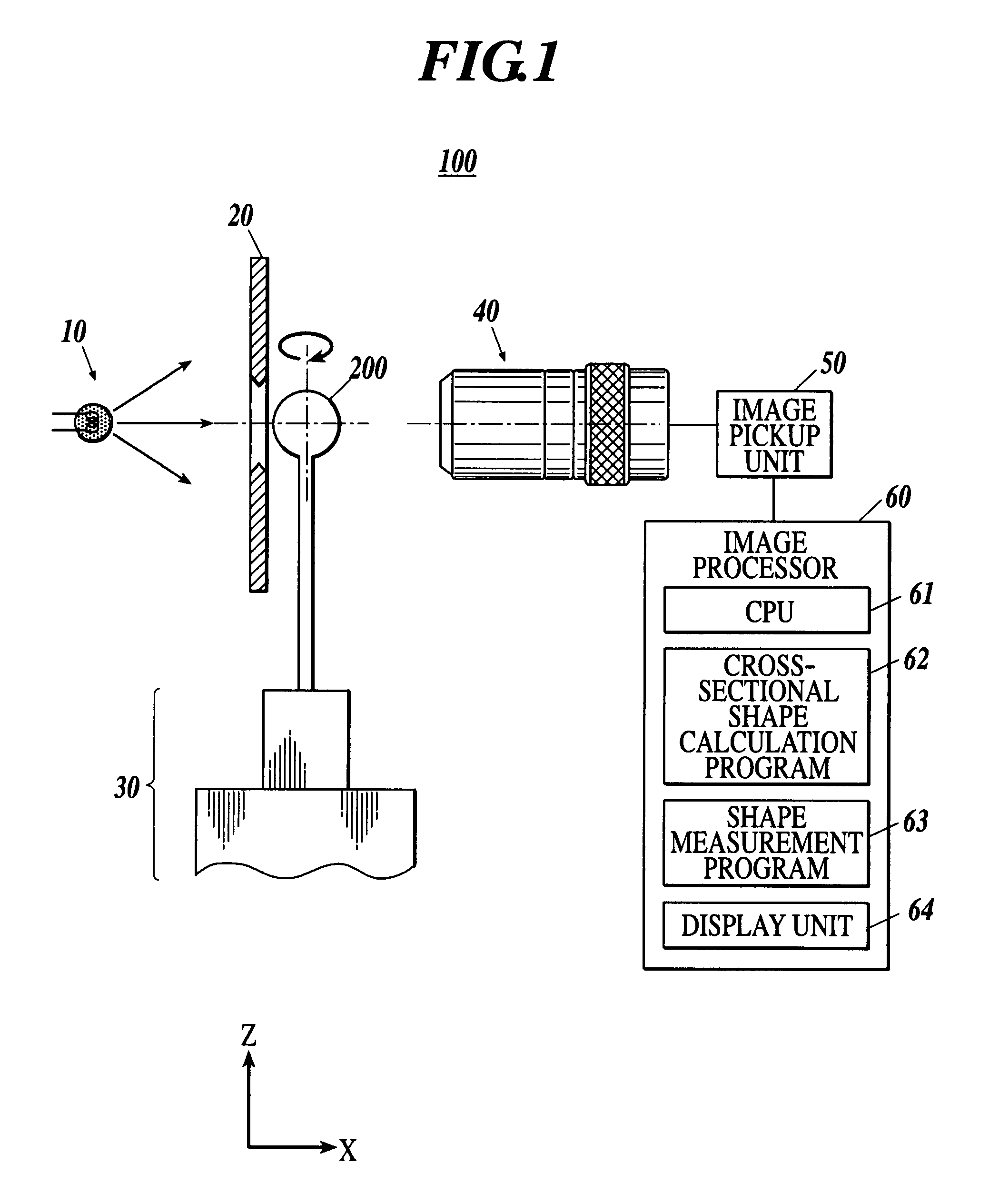
[0054]As shown in FIG. 1, a shape measurement apparatus 100 in Embodiment 1 includes a light source unit 10, an aperture 20, a rotating mechanism 30 for rotating and supporting an object 200 to be measured; a magnifying lens 40; an image pickup unit 50; and an image processor 60. Along the optical axis of light outputted from the light source unit 10, the aperture 20, the object 200 to be measured, the magnifying lens 40, and the image pickup unit 50 are arranged in this order.
[0055]The light source unit 10 uses a point light source for emitting white light for example as shown in FIG. 1 and projects white light to the object 200 to be measured. It is noted that the light source unit 10 is not limited to such a point light source and also may be a surface light source or also may emit light by a discharge lamp, a light-emitting diode, or laser.
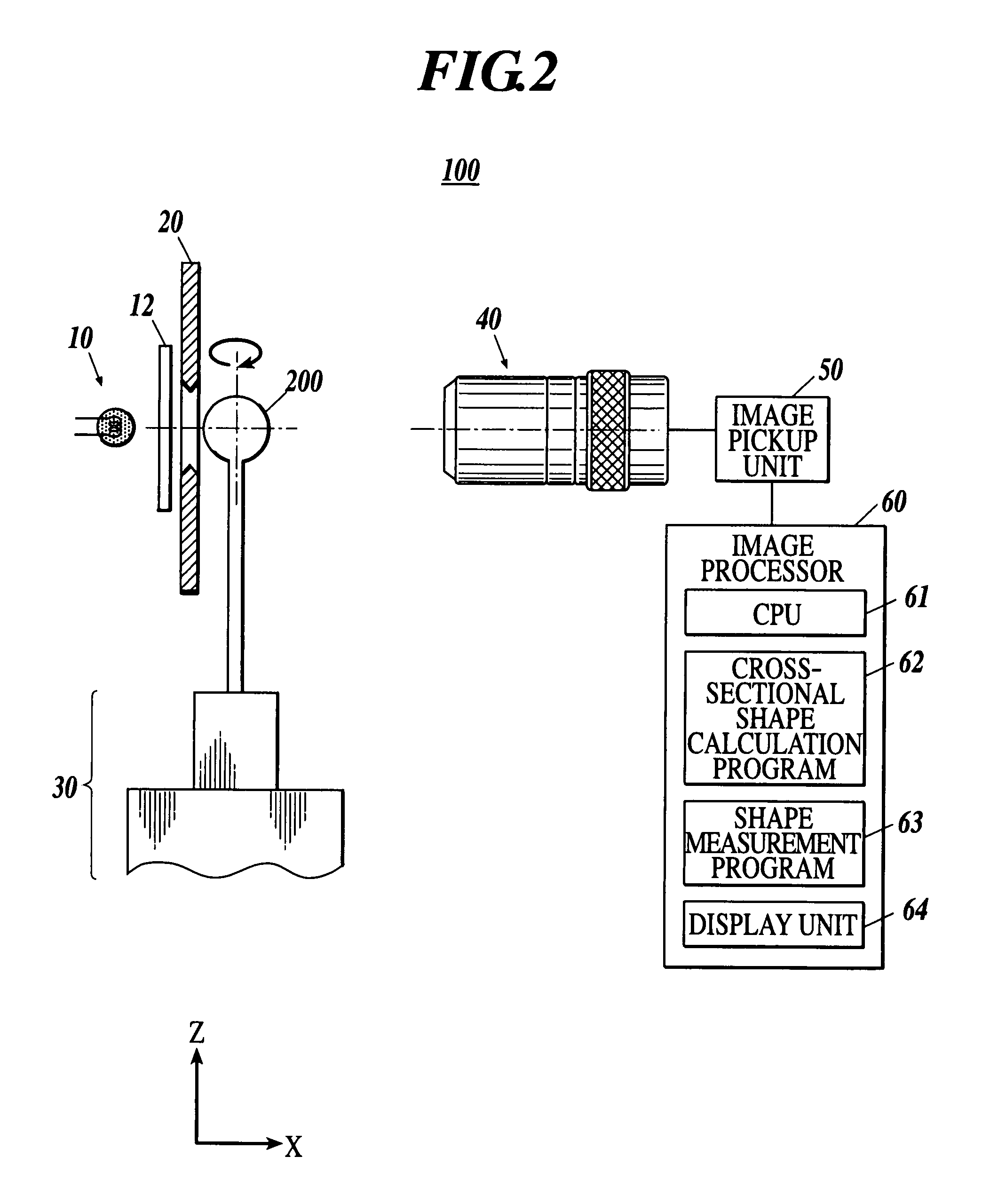
[0056]As shown in FIG. 2, the light source unit 10 also can include a diffuser plate 12 as a diffusing unit between a point light source and ...
embodiment 2
[0094]Next, Embodiment 2 of the shape measurement apparatus according to the present invention will be described with reference to FIG. 7. The basic structure of Embodiment 2 is the same as that of Embodiment 1. However, the structure of Embodiment 2 is different from that of Embodiment 1 in that the magnifying lens 40 is replaced with a telecentric lens 45.
[0095]According to the structure as described above, by the telecentric lens 45, it is possible to form an image by using only light parallel to the optical axis among light passing through the opening 21 of the aperture 20. Therefore, an error of the size of the image can be suppressed, and a more preferable shape measurement can be performed.
[0096]In Embodiment 2, a method for measuring the shape of the object 200 to be measured by the shape measurement apparatus 300 is the same as that of Embodiment 1.
embodiment 3
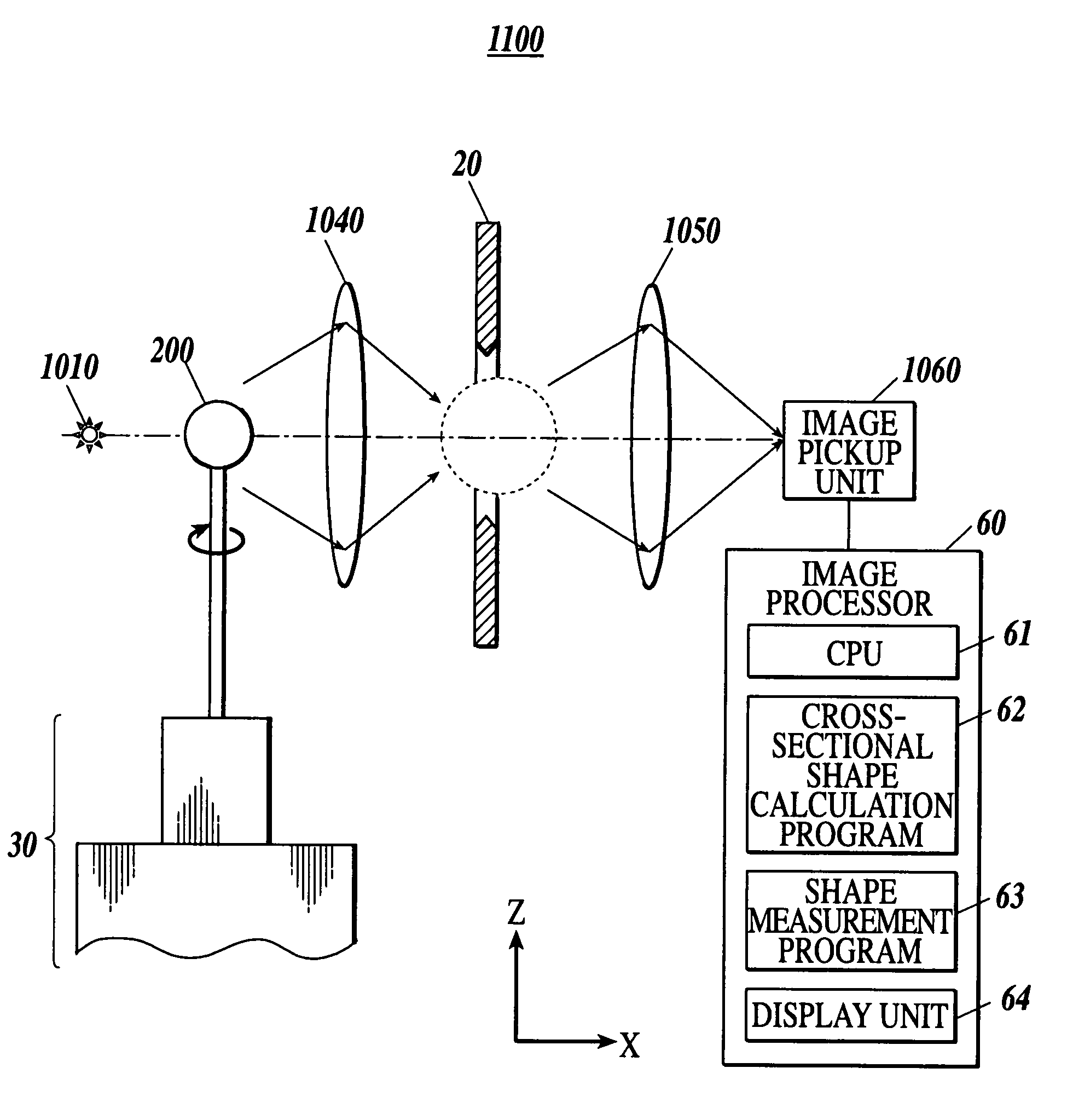
[0097]As shown in FIG. 8, a shape measurement apparatus 1100 in Embodiment 3 includes a light source unit 1010, the aperture 20, the rotating mechanism 30, an objective lens 1040 as the first lens, an objective lens 1050 as the second lens, an image pickup unit 1060, and the image processor 60. Along the optical axis of light outputted from the light source unit 1010, an object 200 to be measured, the objective lens 1040, the aperture 20, the objective lens 1050, and the image pickup unit 1060 are arranged in this order. It is noted that the same components as those of Embodiments 1 and 2 are denoted with the same reference numerals and only components different from those of Embodiments 1 and 2 will be described.
[0098]For example, as shown in FIG. 8, the light source unit 1010 uses a point light source outputting white light to project white light to the object to be measured 1200. It is noted that the light source unit is not limited to such a point light source and also may be a ...
PUM
 Abstract
Description
Claims
Application Information
 - R&D
- Intellectual Property
- Life Sciences
- Materials
- Tech Scout
- Unparalleled Data Quality
- Higher Quality Content
- 60% Fewer Hallucinations
Browse by: Latest US Patents, China's latest patents, Technical Efficacy Thesaurus, Application Domain, Technology Topic, Popular Technical Reports.
© 2025 PatSnap. All rights reserved.Legal|Privacy policy|Modern Slavery Act Transparency Statement|Sitemap|About US| Contact US: help@patsnap.com