Eureka AIR delivers breakthrough ideas for toughest innovation challenges, trusted by R&D personnel around the world.

Photoelectric measuring device for photoelectric detection

A photoelectric measurement and photoelectric detection technology, which is applied in the direction of measuring devices, measuring instruments, photovoltaic power generation, etc., can solve the problems of inconvenient use of surveying and mapping, waste of manpower and material resources, and inconvenient angle adjustment, so as to avoid tedious and unstable adjustment and save measurement. Time and the effect of improving measurement efficiency

Pending Publication Date: 2022-07-12
厦门海洋职业技术学院
View PDF0 Cites 0 Cited by
  • Summary
  • Abstract
  • Description
  • Claims
  • Application Information

AI Technical Summary

Problems solved by technology

[0003] In surveying and mapping, photoelectric measurement technology is often used to measure physical quantities such as angles and distances. However, traditional photoelectric measuring devices are often difficult to ensure horizontal measurement operations due to uneven bottoms during surveying and mapping operations, which in turn leads to photoelectric measurement. The measurement accuracy of the measuring device is reduced. In addition, the angle of the traditional photoelectric measuring device is often inconvenient to adjust during surveying and mapping, which makes it inconvenient to use the surveying and mapping, which leads to low efficiency of physical quantity surveying and mapping, waste of manpower and material resources, and the surveying and mapping height of the traditional photoelectric measuring device It is often inconvenient to adjust, which leads to its stable installation and cumbersome operation, which is not conducive to the use of photoelectric devices for surveying and mapping

Method used


Image

  • Photoelectric measuring device for photoelectric detection
  • Photoelectric measuring device for photoelectric detection
  • Photoelectric measuring device for photoelectric detection

Examples


Embodiment Construction

[0029] The technical solutions in the embodiments of the present invention will be clearly and completely described below with reference to the accompanying drawings in the embodiments of the present invention. Obviously, the described embodiments are only a part of the embodiments of the present invention, rather than all the embodiments. Based on the embodiments of the present invention, all other embodiments obtained by those of ordinary skill in the art without creative efforts shall fall within the protection scope of the present invention.

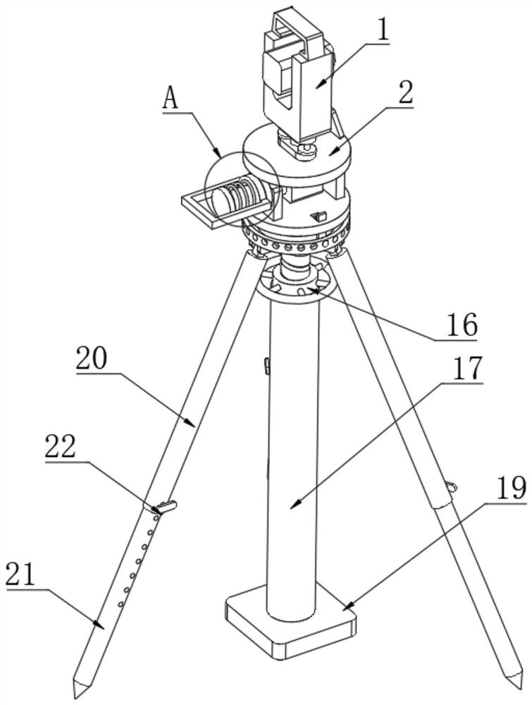
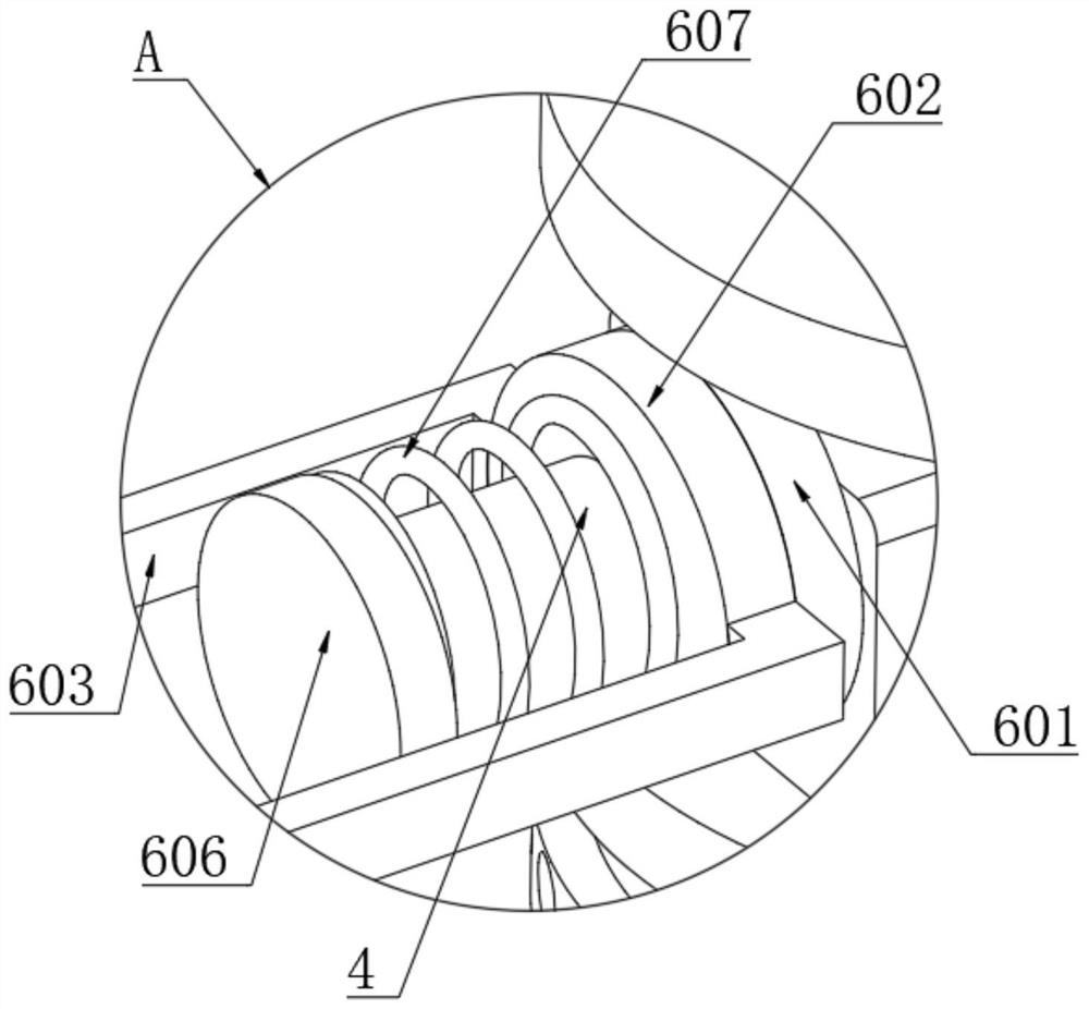
[0030] see Figure 1-9 , a photoelectric measuring device for photoelectric detection, including a measuring device 1, the bottom of the measuring device 1 is fixedly provided with a fixed table 2, the bottom of the fixed table 2 is fixedly provided with a connecting block 3 for rotational adjustment, and the side of the connecting block 3 is fixed A connecting shaft 4 is fixedly arranged, and both ends of the connecting shaft 4 pass...


PUM


Abstract

The invention relates to the technical field of photoelectric measurement equipment, and discloses a photoelectric measurement device for photoelectric detection, which comprises a measurer, a fixed table is fixedly arranged at the bottom of the measurer, a connecting block for rotary adjustment is fixedly arranged at the bottom of the fixed table, and a connecting shaft is fixedly arranged on the side surface of the connecting block. The two ends of the connecting shaft penetrate through the connecting blocks, and the connecting shaft is rotationally sleeved with two connecting plates. According to the photoelectric measurement device for photoelectric detection, through arrangement of a connecting block and a connecting shaft, a pull handle is pulled, and the pull handle drives a sliding disc to slide, so that a limiting block is separated from a limiting hole in a fixed disc, the connecting block drives a fixed table to rotate, and angle adjustment is performed on a measurer at the top of the fixed table; the levelness of the measurer is ensured to be adjusted, so that the levelness measurement of the measurer can be ensured, and the physical quantity surveying and mapping precision of the photoelectric measuring device is further improved.

Description

technical field [0001] The invention relates to the technical field of photoelectric measuring equipment, in particular to a photoelectric measuring device for photoelectric detection. Background technique [0002] Photoelectric measurement refers to the use of optical fiber communication and optoelectronic devices to measure various physical quantities at high potentials. It has high sensitivity, light weight, small size, and strong anti-electromagnetic interference. The physical quantities are more precise. [0003] During surveying and mapping, photoelectric measurement technology is often used to measure physical quantities such as angles and distances. However, traditional photoelectric measurement devices are often difficult to ensure horizontal measurement operations due to the uneven bottom of traditional photoelectric measurement devices during surveying and mapping operations. The measurement accuracy of the measuring device is reduced. In addition, the angle of t...

Claims


Application Information

Patent Timeline
Patent Type & Authority Applications(China)
IPC IPC(8): F16M11/04F16M11/12F16M11/16F16M11/18F16M11/32G01C15/00
CPCF16M11/046F16M11/18F16M11/12F16M11/16F16M11/32G01C15/00F16M2200/024F16M2200/028Y02E10/50
Inventor 赵玉超林志谋陈秉试
Owner 厦门海洋职业技术学院
Why Eureka
Eureka Blog
Learn More