
Large signal polar modulated power amplifier

Active Publication Date: 2009-09-22
QORVO US INC
View PDF26 Cites 28 Cited by
  • Summary
  • Abstract
  • Description
  • Claims
  • Application Information

AI Technical Summary

Benefits of technology

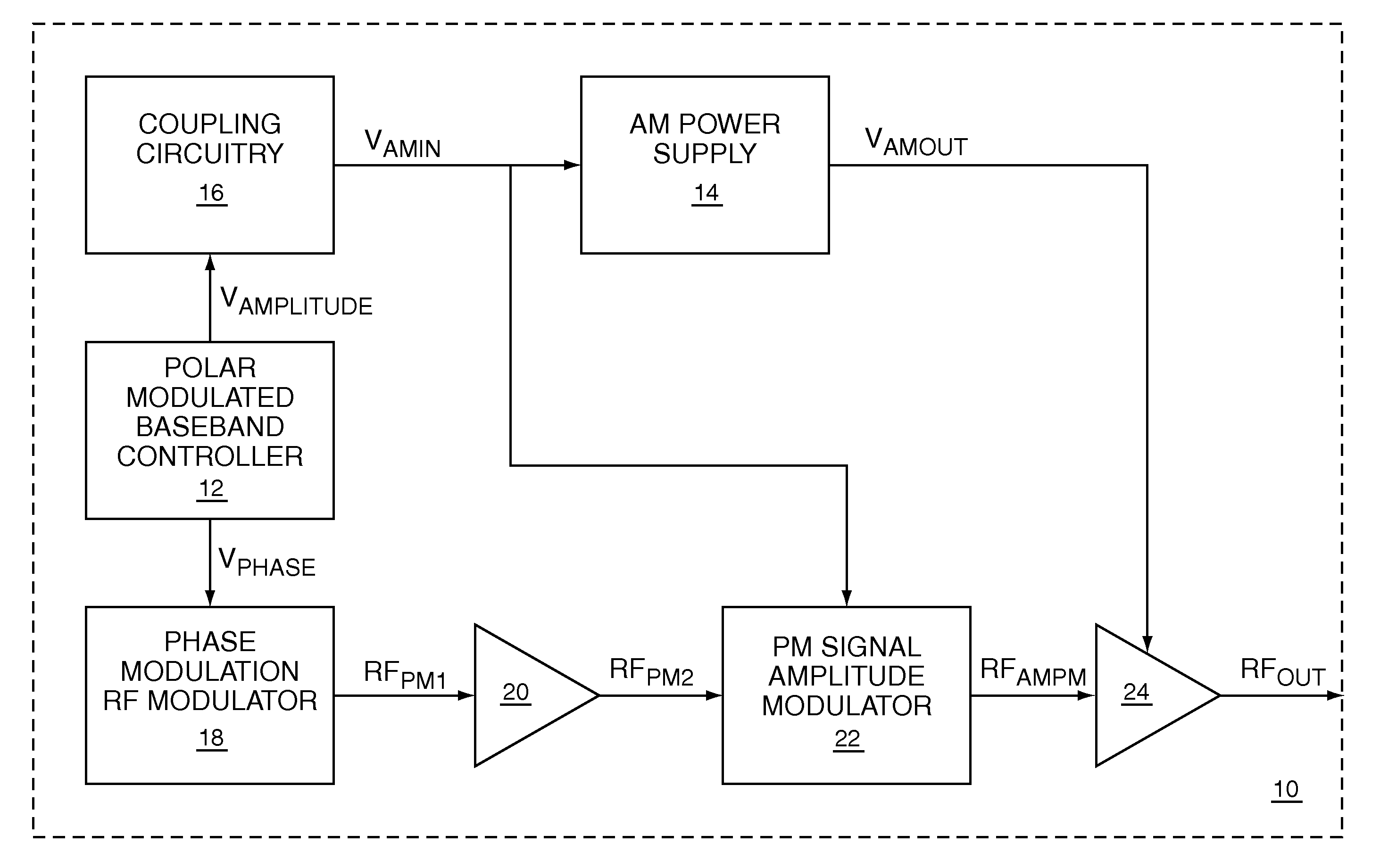
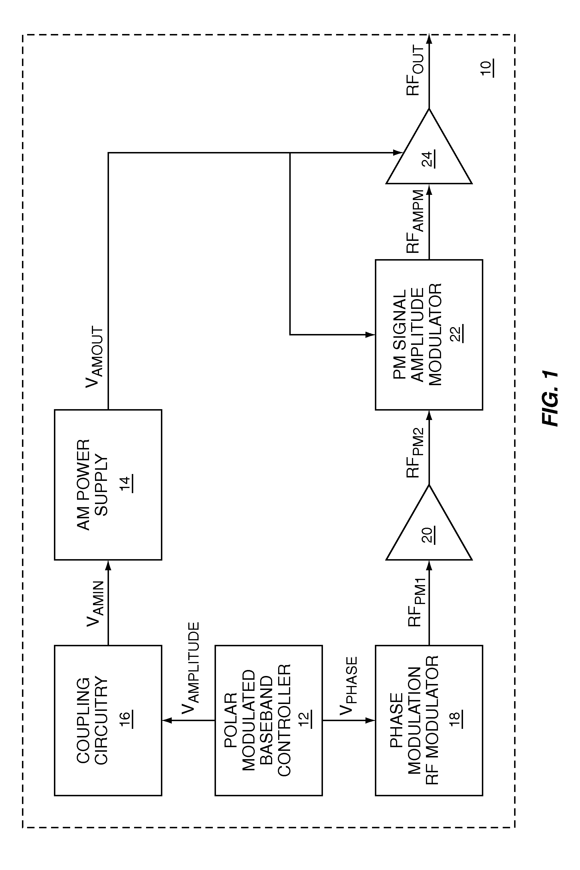
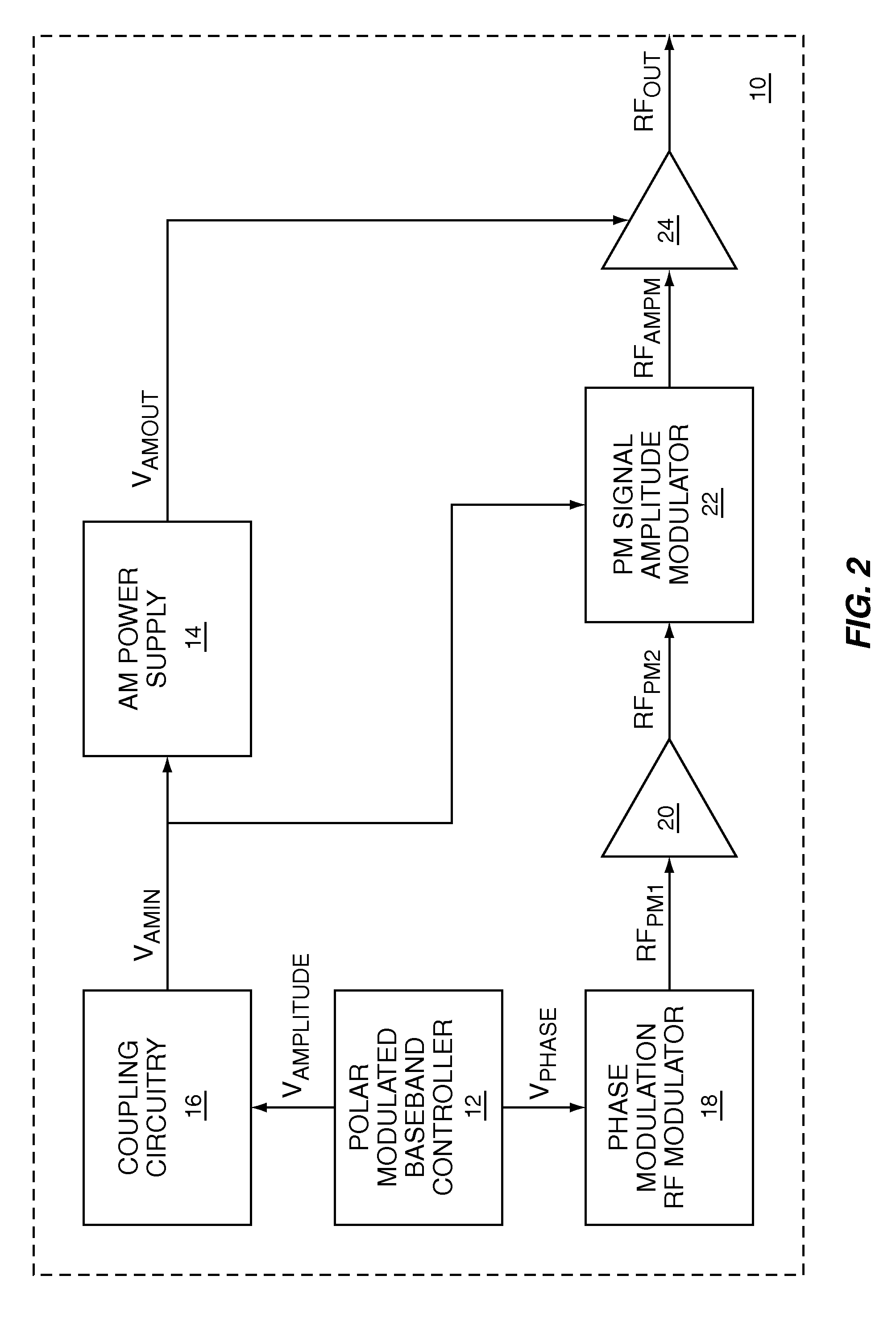
[0004]Polar modulation input signals to a polar modulated power amplifier include a phase modulated (PM) input signal, which feeds a power amplifier input, and an amplitude modulated (AM) input signal, which provides an envelope supply voltage for the power amplifier. The present invention is a large signal polar modulated power amplifier that extends the effective amplitude range of AM input signals that can be handled by the power amplifier by amplitude modulating the PM input signal using the AM input signal. Amplitude modulating the PM input signal effectively lowers the amplitude of the PM input signal when the amplitude of the AM input signal is lowered, which maintains adequate headroom between the power amplifier's signal input and envelope supply voltage input in the presence of large amplitude AM input signals. As a result, the power amplifier can amplify larger amplitude AM input signals than traditional power amplifier designs.

Problems solved by technology

However, in a polar modulated system, large signal amplitude modulation can interfere with proper operation of phase modulated (PM) signals.
In the presence of large signal amplitude modulation signals, the voltage at the collector of the NPN transistor may drop below the voltage at the base of the NPN transistor, resulting in forward biasing of the base-to-collector junction, which distorts the amplified PM RF signal and degrades the RF spectrum.

Method used


Image

  • Large signal polar modulated power amplifier
  • Large signal polar modulated power amplifier
  • Large signal polar modulated power amplifier

Examples


Embodiment Construction

[0012]The embodiments set forth below represent the necessary information to enable those skilled in the art to practice the invention and illustrate the best mode of practicing the invention. Upon reading the following description in light of the accompanying drawing figures, those skilled in the art will understand the concepts of the invention and will recognize applications of these concepts not particularly addressed herein. It should be understood that these concepts and applications fall within the scope of the disclosure and the accompanying claims.

[0013]Polar modulation input signals to a polar modulated power amplifier include a PM input signal, which feeds a power amplifier input, and an AM input signal, which provides an envelope supply voltage for the power amplifier. The present invention is a large signal polar modulated power amplifier that extends the effective amplitude range of AM input signals that can be handled by the power amplifier by amplitude modulating the...


PUM


Abstract

Polar modulation input signals to a polar modulated power amplifier include a phase modulated (PM) input signal, which feeds a power amplifier input, and an amplitude modulated (AM) input signal, which provides an envelope supply voltage for the power amplifier. The present invention is a large signal polar modulated power amplifier that extends the effective amplitude range of AM input signals that can be handled by the power amplifier by amplitude modulating the PM input signal using the AM input signal. Amplitude modulating the PM input signal effectively lowers the amplitude of the PM input signal when the amplitude of the AM input signal is lowered, which maintains adequate headroom between the power amplifier's signal input and envelope supply voltage input in the presence of large amplitude AM input signals. As a result, the power amplifier can amplify larger amplitude AM input signals than traditional power amplifier designs.

Description

FIELD OF THE INVENTION[0001]The present invention relates to Radio Frequency (RF) power amplifiers used in RF communications circuitry.BACKGROUND OF THE INVENTION[0002]With the growth of the wireless communications industry, wireless communications protocols become more sophisticated and demanding in their requirements for complex modulation schemes and narrow channel bandwidths. The ultimate goal is to encode as much digital information as possible in a given channel. One such modulation scheme for encoding digital information is polar modulation. Polar modulated RF transmitters utilize both amplitude modulation and phase modulation to maximize the amount of information that can be encoded with minimum bandwidth. By using multiple combinations of phase and amplitude, multiple digital bits of information can be represented. Large signal amplitude modulation allows several distinct levels of modulation with adequate noise margins for reliable encoding of digital data. However, in a p...

Claims


Application Information

Patent Timeline
IPC IPC(8): H04B1/66
CPCH03F1/0211H03F3/191H03F3/245H04B1/0483H03F2200/324H03F2200/411H03F2200/451H03F2200/108
Inventor JOHNSON, JACKIEBOSLEY, RYANZYBURA, MICHAEL F.
Owner QORVO US INC
Learn More