
Convertor shared by multiple virtual private networks

a virtual private network and converter technology, applied in the field of VPN gateways, can solve the problems of media triangulation problems, equipment cost or configuration complexity, and additional hardware costs, and achieve the effects of reducing network costs, reducing the number of software modules, and avoiding capital costs and maintenance costs of additional equipmen

Inactive Publication Date: 2009-09-22
RPX CLEARINGHOUSE
View PDF33 Cites 14 Cited by
  • Summary
  • Abstract
  • Description
  • Claims
  • Application Information

AI Technical Summary

Benefits of technology

"The present invention provides an improved apparatus and methods for interfacing multiple virtual private networks (VPNs) with external networks. The apparatus includes a converter that can receive information from the VPNs and convert the format of the information for transmission over the external network. This reduces network costs and complexity, as well as the need for multiple converters. The converter can interface with call servers and can handle various types of communication sessions. It can also determine the identity of the VPN and pass it to the external network. The invention provides a more efficient and flexible solution for interfacing multiple VPNs with external networks."

Problems solved by technology

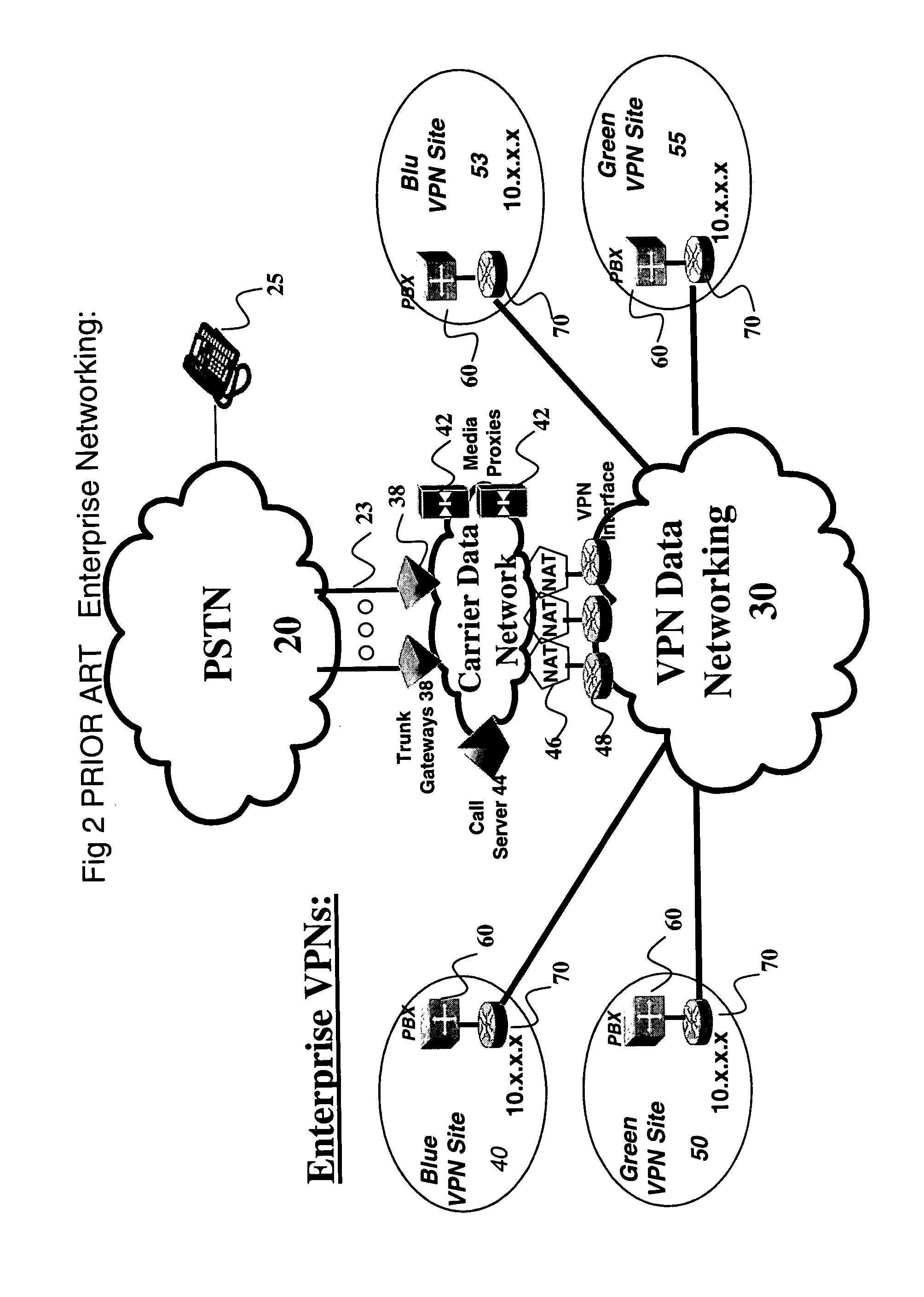
Unfortunately, NAT has the side effect of modifying the IP address and port address of devices in the private network when they communicate with the public network.
A number of techniques have been implemented to get around the NAT problem but all have some form of drawbacks, in term of equipment cost or configuration complexities.
However they are costly additional hardware, and may not be on the natural path of the media resulting in media triangulation problems and added delay.
Alternatively, the STUN protocol can be used by the gateway, but this results in all calls being public and negates the other advantages of using the VPNs for such traffic.
Because of the NAT, the call server cannot simply provide the enterprise media gateway and the trunk gateway with each others respective IP addresses and let the gateways send VoIP packets to each other as would normally be the case.
They add considerable complexity and cost in terms of capital expenditure and running costs.
Such costs escalate rapidly as the number of VPNs increases.

Method used


Image

  • Convertor shared by multiple virtual private networks
  • Convertor shared by multiple virtual private networks
  • Convertor shared by multiple virtual private networks

Examples


Embodiment Construction

FIG. 3, Embodiment of VPN Converter

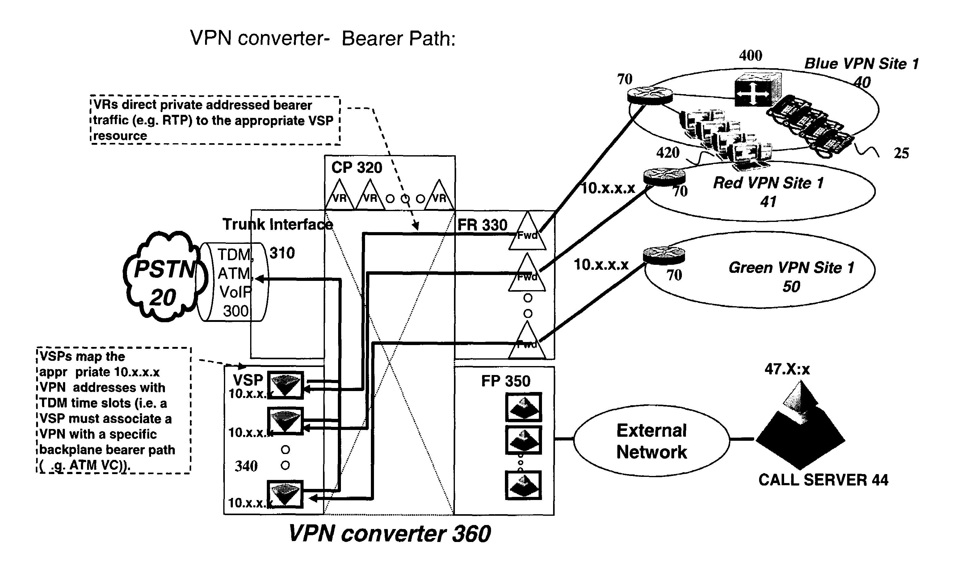
[0068]FIG. 3 shows a first embodiment of the invention. As in FIG. 2, voice traffic is handled by the VPN data networking environment. A simplified interface between this environment, having a number of VPNs, and the PSTN 20, is provided by the VPN converter 100. In this example, the external networks are exemplified by the carrier data network and the PSTN. The call server is an example of an entity in the address space of the carrier data network, and PSTN telephones are examples of entities in the address space of the PSTN. There is a VPN gateway 110 which provides an interface from the VPNs to the call server, and the VPN converter provides an interface to the PSTN. The VPN gateway and the VPN converter are shared by a number of VPNs. As shown diagrammatically, the VPN converter at the interface to the PSTN combines the functions of a router, a NAT, and a converter. The PSTN trunks are connected directly to this VPN converter without the need f...


PUM


Abstract

A VPN converter for interfacing two or more VPNs to an external network receives information relating to a communication session between an entity in any of the VPNs and the external network and converts a format such as an encoding or transmission format of the information, e.g. between VoIP packets and TDM signals for the PSTN. The converter is under the control of a call server and carries out routing and NAT functions. It determines which VPN the information relates to. By sharing the call server and converter between many VPNs, the amount of equipment can be reduced.

Description

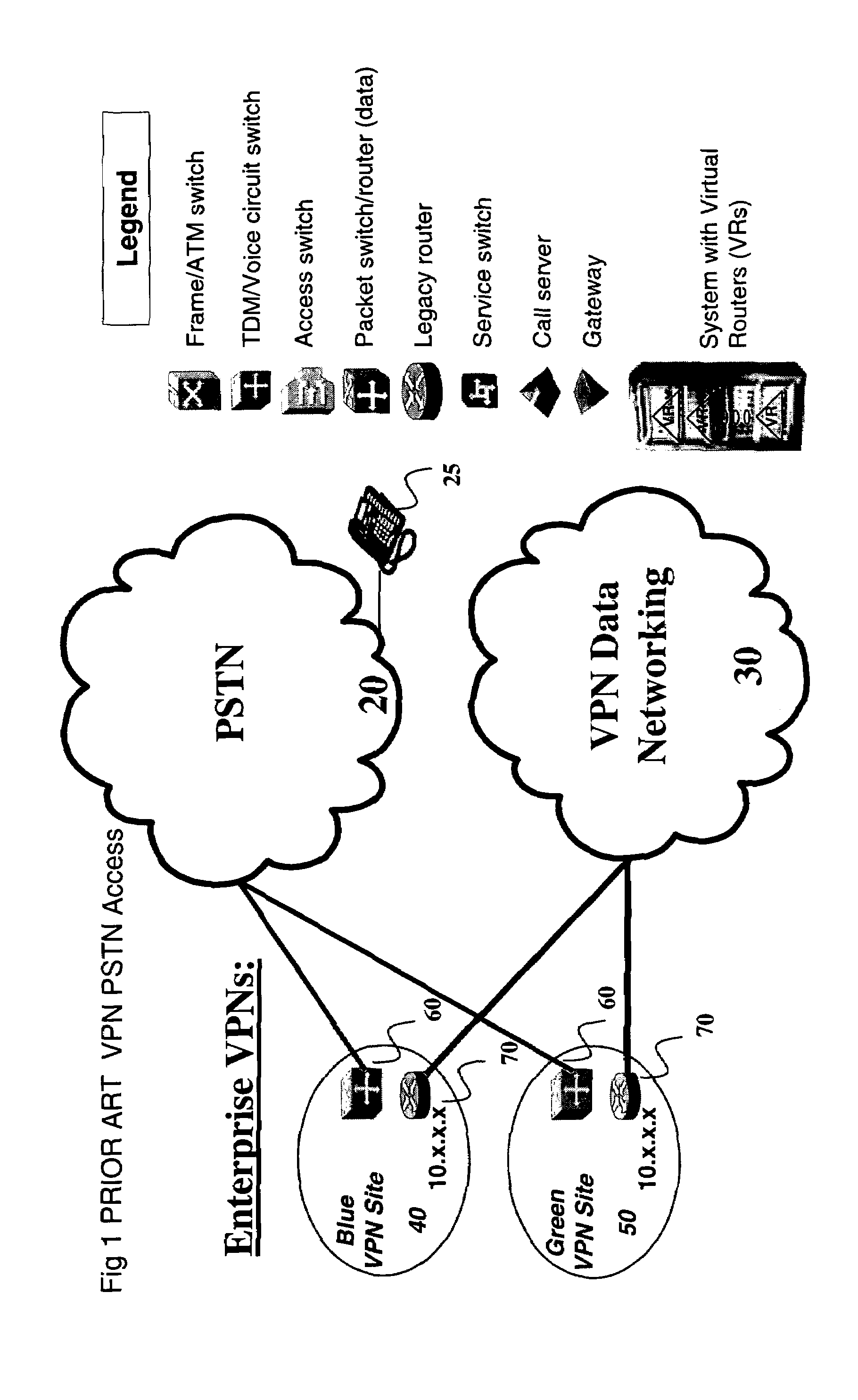
RELATED APPLICATIONS[0001]This invention relates to copending U.S. patent application Ser. Nos. 10 / 675,063 and 10 / 675,645 respectively entitled “Gateway shared by multiple virtual private networks” and “Media proxy having interface to multiple virtual private networks” of even filing date, and hereby incorporated by reference.FIELD OF THE INVENTION[0002]This invention relates to VPN gateways for interfacing two or more VPNs (Virtual private networks or virtual packet networks), to methods and software for such apparatus, and to methods of offering a VPN service over such apparatus.BACKGROUND TO THE INVENTION[0003]A broad definition of a VPN is ‘any network built upon a public network and partitioned for use by individual customers’. This results in public frame relay, X.25, and ATM networks being considered as VPNs. These types of VPNs are generically referred to as Layer 2 VPNs. Another form of VPNs are networks constructed across shared IP backbones, referred to as ‘IP VPNs’ or In...

Claims


Application Information

Patent Timeline
Patent Type & Authority Patents(United States)
IPC IPC(8): H04L12/66
CPCH04L12/66H04L12/4641
Inventor MITCHELL, JULIANSYLVAIN, DANYLARRIGAN, SCOTT
Owner RPX CLEARINGHOUSE
Learn More