Variable fluid dispenser
a dispenser and variable technology, applied in the direction of liquid transferring devices, liquid/solution decomposition chemical coatings, superimposed coating processes, etc., can solve the problems of delay in valve opening and closing, response time that delays the opening and closing of the valve, and the valve itself has a rate of opening and closing that cannot be controlled, so as to achieve the effect of facilitating the flow ra
- Summary
- Abstract
- Description
- Claims
- Application Information
AI Technical Summary
Benefits of technology
Problems solved by technology
Method used
Image

Examples
embodiment 100
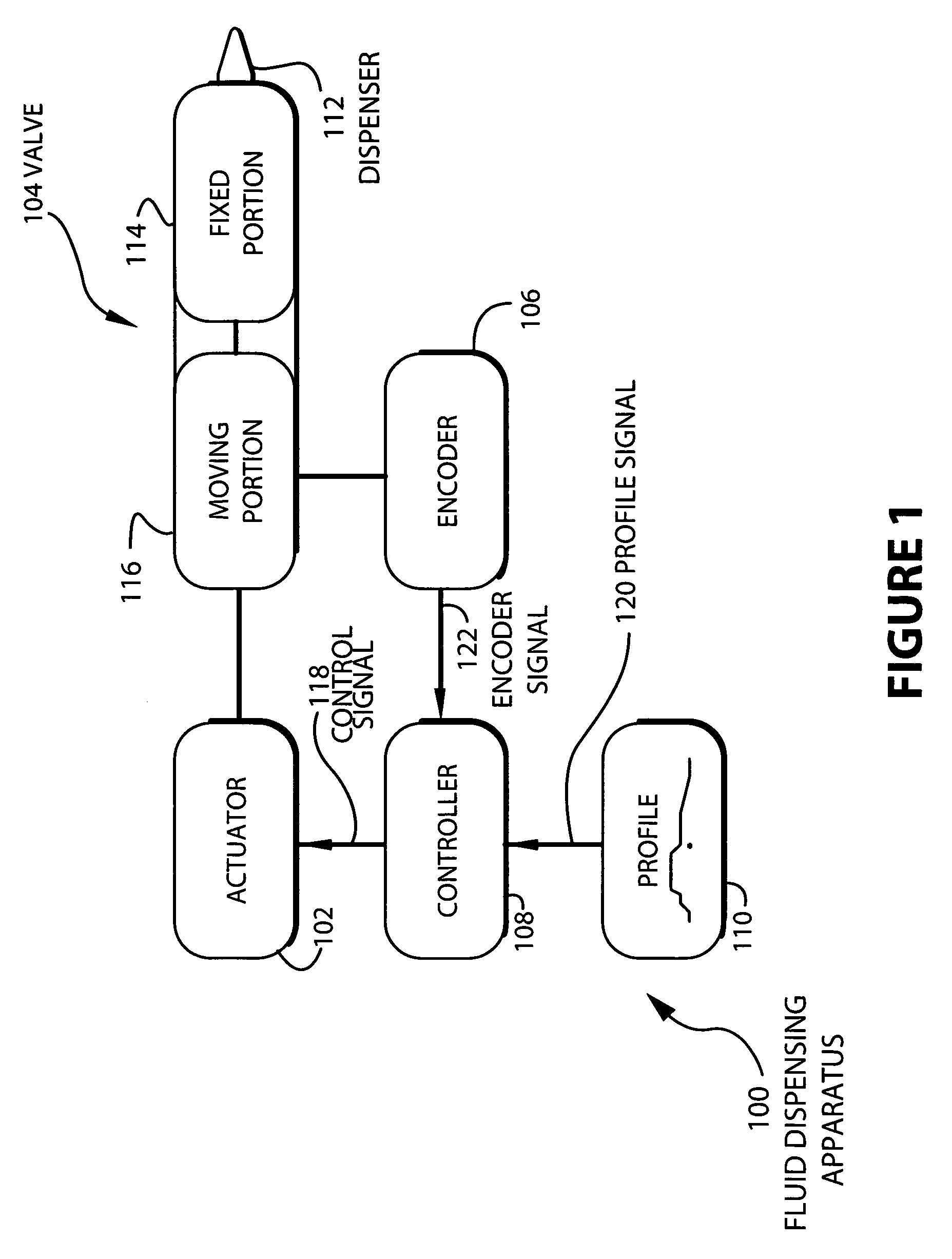
[0023]The embodiment 100 may be used to dispense fluids in various applications for different industries. For example, in can manufacturing, the system may be used to dispense liner compound (sealant) to the can ends prior to assembly on a can body. In another example, the system may be used to dispense caulking, glue, or adhesive for various assembly tasks, wherever these materials are to be dispensed in a controlled manner.
[0024]The actuator 102 is a device that causes mechanical motion between the fixed portion 114 and moving portion 116 of the valve. The moving portion 116 of the valve 104 may fit together with the fixed portion 114 so that when both portions are in contact, fluid cannot flow between them. When the portions separate, a gap is created through which a fluid may flow. This gap may vary proportionately with the distance between the moving portion 116 of the valve 104, and the fixed portion 114 of the valve 104 so that fluid flow increases as the distance between the...
embodiment 200
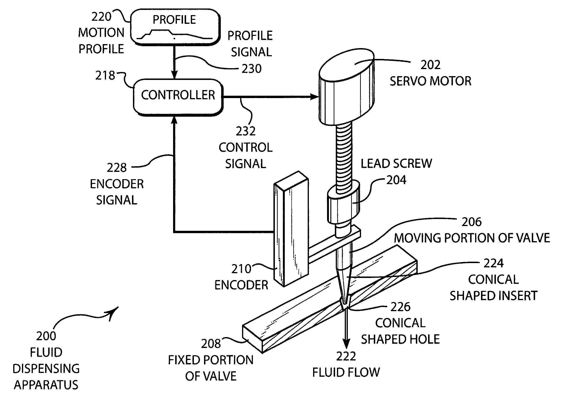
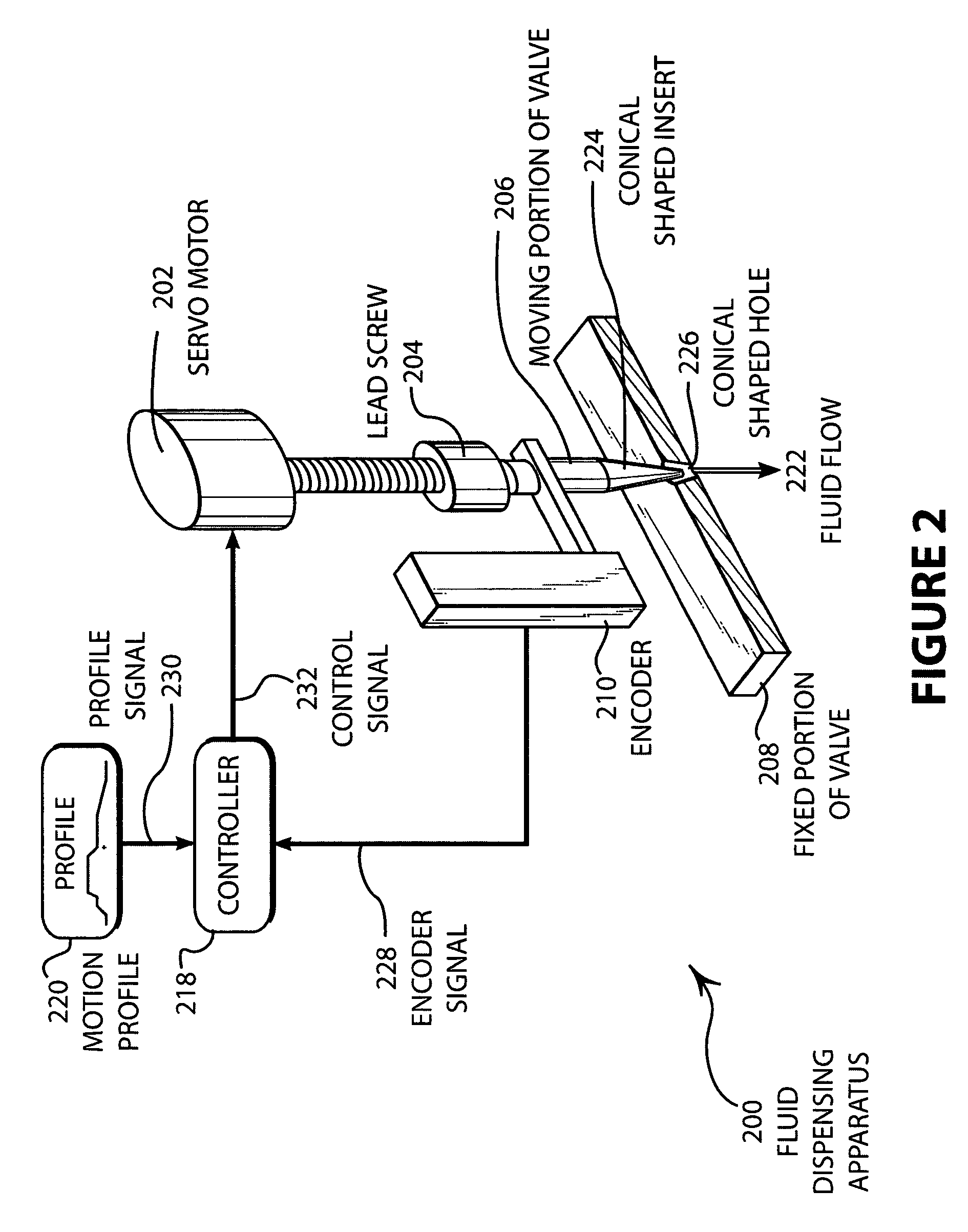
[0034]FIG. 2 illustrates an embodiment 200 having a lead screw driven actuator. A servo-motor 202 is connected to a lead screw 204 that drives the moving portion 206 of the valve with respect to the fixed portion 208 of the valve. An encoder 210 is mounted directly to the moving portion 206 and / or the servo-motor 202. The output of the encoder 210 is an encoder signal 228 that indicates the position of the moving portion 206. The encoder signal 228 is connected to the controller 218 that controls the servo-motor 202 by comparing the profile signal 230 with the encoder signal 228. If a difference exists, a control signal 232 is generated that can comprise any desired type of control signal, as disclosed above, by the controller 218 and applied to the servo-motor 202 so that the motion of the moving portion 206 of the valve follows the motion profile 220.
[0035]The flow of the fluid 222 may be regulated by a conically shaped insert 224 that may fit into a conically shaped hole 226. Whe...
embodiment 300
[0045]FIG. 3 is a schematic representation of an embodiment 300 of the present invention showing a rack and pinion driven valve. The valve 304 may have a moving portion 306 and a fixed portion 308 that are adapted to fit into each other and prevent any fluid flow. The rack and pinion 310 may cause the moving portion 306 of the valve to translate when the motor 302 rotates. As the moving portion of the valve 306 is moved by the rack and pinion 310, the position and / or velocity of the moving portion 306 is captured by an encoder 312 mounted to the shaft of the motor 302 and / or an encoder mounted to the moving piece of the valve. The controller 314 compares the input from the encoder 312 with the desired profile 316 to control the motor 302.
[0046]The embodiment 300 illustrates a mechanism whereby a rotational motion from the motor 302 may be translated to a linear motion of the moving portion 306 of the valve in a proportional manner. The mechanism further allows the axis of the motor ...
PUM
| Property | Measurement | Unit |
|---|---|---|
| time | aaaaa | aaaaa |
| size | aaaaa | aaaaa |
| response time | aaaaa | aaaaa |
Abstract
Description
Claims
Application Information
 - R&D
- Intellectual Property
- Life Sciences
- Materials
- Tech Scout
- Unparalleled Data Quality
- Higher Quality Content
- 60% Fewer Hallucinations
Browse by: Latest US Patents, China's latest patents, Technical Efficacy Thesaurus, Application Domain, Technology Topic, Popular Technical Reports.
© 2025 PatSnap. All rights reserved.Legal|Privacy policy|Modern Slavery Act Transparency Statement|Sitemap|About US| Contact US: help@patsnap.com