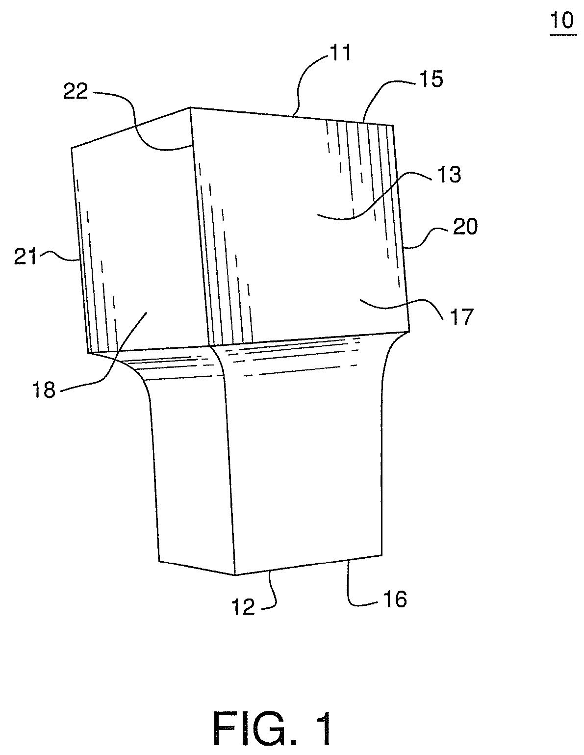
Cornice corner cap and methods related thereto
a technology for corner caps and trim parts, applied in the field of siding products, can solve the problems of increasing labor and expertise for siding installation as corner structures of buildings, increasing the cost of wooden products, and increasing the cost of wood products, so as to reduce the intrusion of water or insects
- Summary
- Abstract
- Description
- Claims
- Application Information
AI Technical Summary
Benefits of technology
Problems solved by technology
Method used
Image
Examples
example i
[0068]In a first trial, a force gauge with a hook was used to pull the cornice molding, in the absence of a cornice molding corner cap, from the receiver until the molding was dislodged from the receiver. The pulling force was directed perpendicularly away from the wall near the end of the molding strip. The force was measured to remove the molding from the receiver channel.
example 2
[0069]In a second trial, a cornice molding corner cap of the present invention was installed over cornice molding accessory strips mounted to the wall using F-channel receiver strips nailed to the wall. A pushing force was imposed against the cornice molding corner cap at a lateral edge of the cap adjacent to one of the molding strips in a direction parallel to a first molding strip toward the end of the molding strip covered by the cap. The force was applied to the cap until either the cap was dislodged or the second molding strip, perpendicular to the direction of the applied force, was forced out of the receiver strip. A force transducer was used to measure the imposed force through the course of the test. FIGS. 16 and 16b depict the test in progress with assembly 500, FIG. 16b being slightly later during the test than FIG. 16. A first cornice molding strip 501 was mounted on the wall by receiver strip 504. Second cornice molding strip 502 was mounted on the adjacent wall around ...
example 3
[0070]In a third trial, a cornice molding corner cap of the present invention was installed over cornice molding accessory strips mounted to the wall using F-channel receiver strips nailed to the wall. A pulling force was imposed on the cornice molding corner cap using a force gauge with a hook fixture attached to the end of the force probe. The fixture was hooked over the top of the cap at the corner to engage a force on the cap. The force was imposed along an angle bisecting the legs of the corner and directly away from the wall. That is to say, the force was directed at an angle of 135 degrees from each of the two walls and in the same plane as the mounting of the two molding strips on the surface of the wall. The force was applied to the cap until either the cap was dislodged or at least one of the molding strips was forced out of its respective receiver strip. FIGS. 17 and 17b depict the test in progress with assembly 600, FIG. 17b being slightly later during the test than FIG....
PUM
 Abstract
Description
Claims
Application Information
 - R&D
- Intellectual Property
- Life Sciences
- Materials
- Tech Scout
- Unparalleled Data Quality
- Higher Quality Content
- 60% Fewer Hallucinations
Browse by: Latest US Patents, China's latest patents, Technical Efficacy Thesaurus, Application Domain, Technology Topic, Popular Technical Reports.
© 2025 PatSnap. All rights reserved.Legal|Privacy policy|Modern Slavery Act Transparency Statement|Sitemap|About US| Contact US: help@patsnap.com


