
Modular personal pontoon boat

a technology for pontoon boats and boats, applied in the field of personal pontoon boats, can solve the problems of reducing the buoyancy of the boat, and causing the seam to be easily damaged, so as to achieve the effect of being particularly resistant to punctures

Active Publication Date: 2009-09-15
TILLICUM INT INC
View PDF23 Cites 17 Cited by
  • Summary
  • Abstract
  • Description
  • Claims
  • Application Information

AI Technical Summary

Benefits of technology

The modular design provides enhanced durability, resistance to punctures, and stability across varying temperatures and pressures, ensuring consistent buoyancy and ease of use and storage.

Problems solved by technology

Because they are relatively thin, typical float tubes and pontoons are highly susceptible to puncture, such as from snagging fish hooks, rocks, branches, etc.
Additionally, the sections of their construction are typically heat-welded together, creating seams that can present inherent weakness.
Because of their thinness and pliability, when typical pontoons are punctured, they can collapse and lose their buoyancy.
They can also be difficult to repair.
Once repaired, the membrane may not be as strong as it was before.
Additionally, typical float tubes and pontoons are very susceptible to changes in temperature and barometric pressure.
When temperatures decrease again later in the day and toward evening, the pontoon pressure likewise drops, and the boat may no longer provide sufficient buoyancy.
Another problem with many prior art pontoons is that they are unnecessarily complex in their design.

Method used


Image

  • Modular personal pontoon boat
  • Modular personal pontoon boat
  • Modular personal pontoon boat

Examples


Embodiment Construction

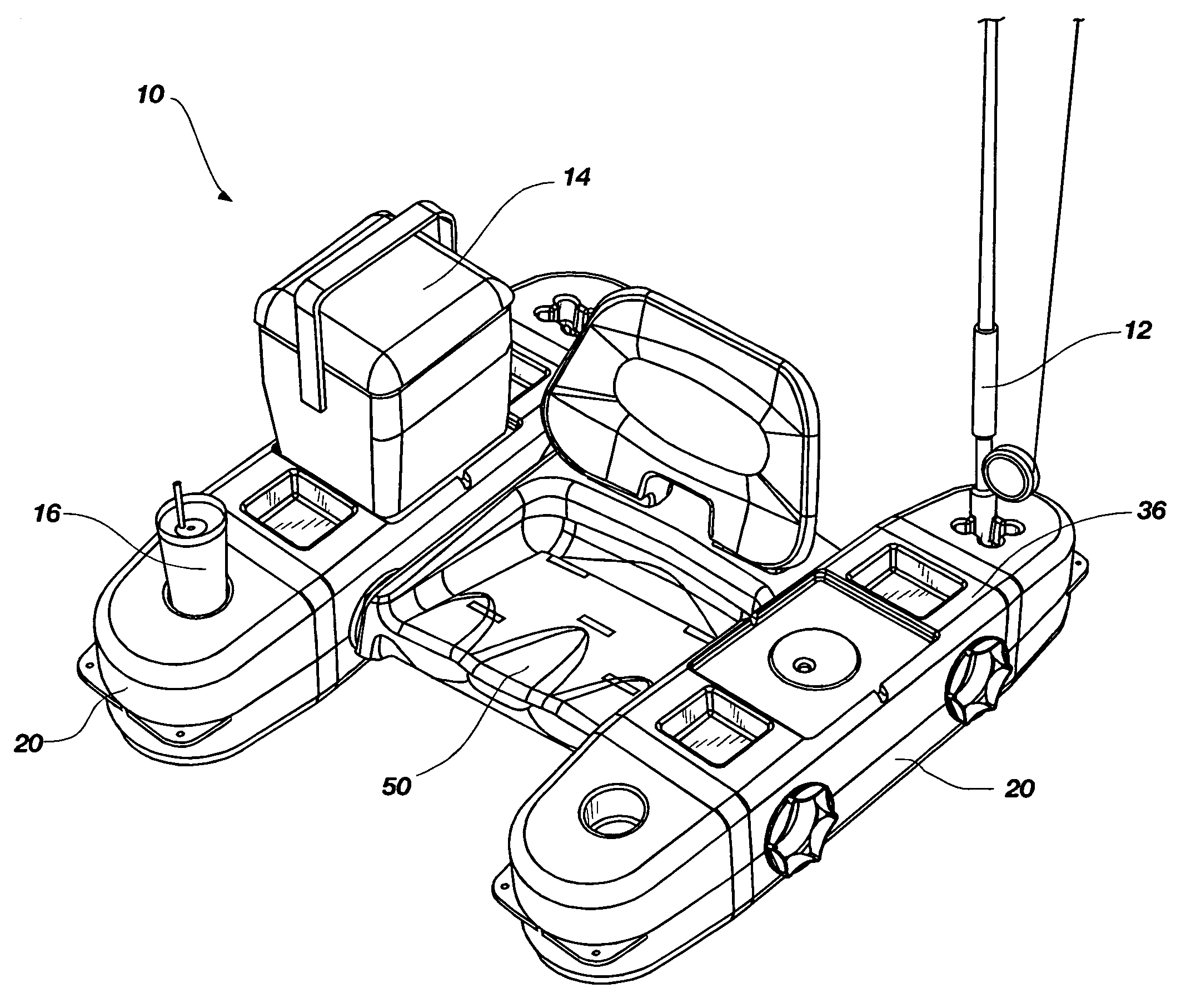
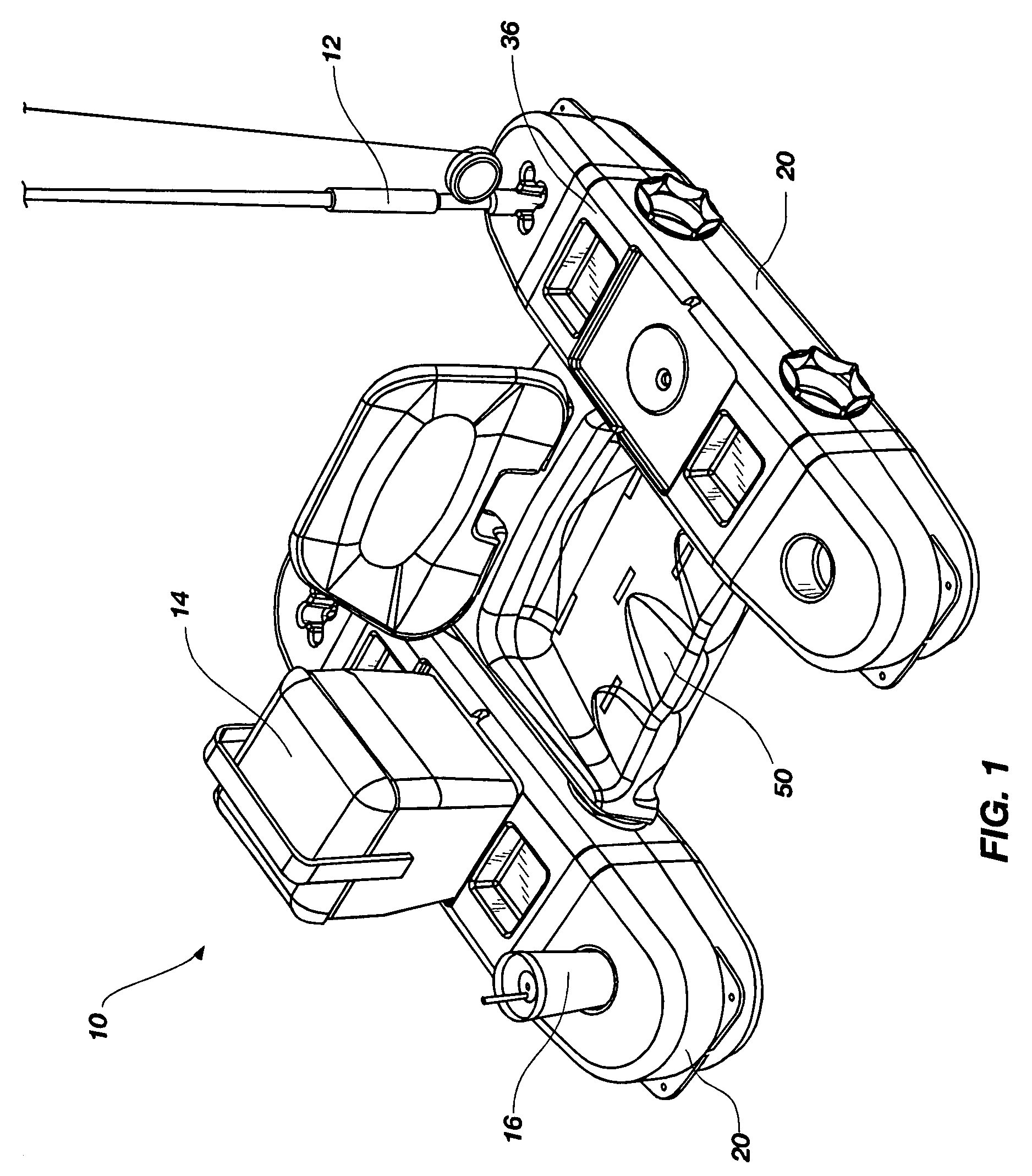
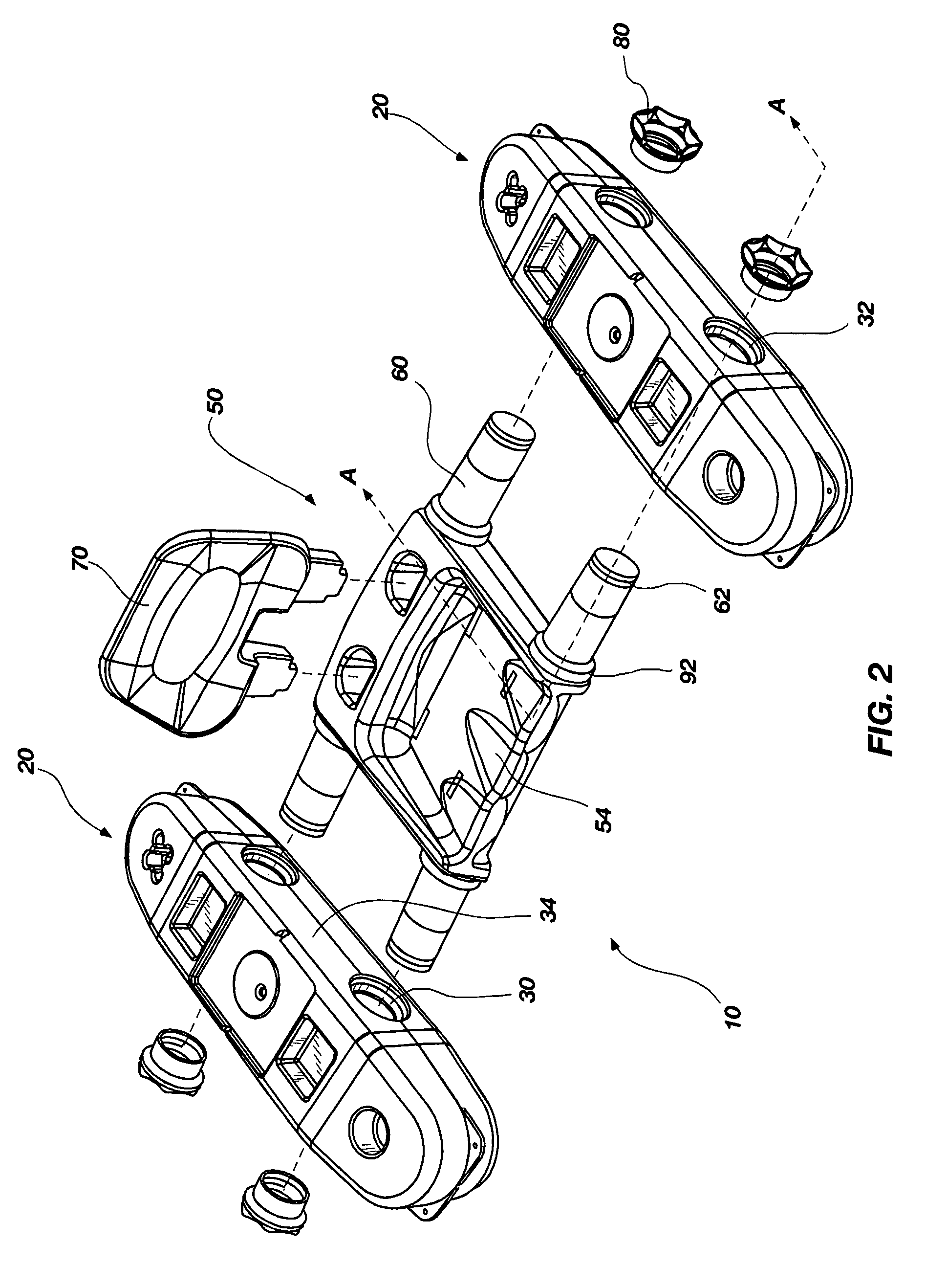
[0033]The following detailed description of exemplary embodiments of the invention makes reference to the accompanying drawings, which form a part hereof and in which are shown, by way of illustration, exemplary embodiments in which the invention may be practiced. While these exemplary embodiments are described in sufficient detail to enable those skilled in the art to practice the invention, it should be understood that other embodiments may be realized and that various changes to the invention may be made without departing from the spirit and scope of the present invention. Thus, the following more detailed description of the embodiments of the present invention is not intended to limit the scope of the invention, as claimed, but is presented for purposes of illustration only and not limitation to describe the features and characteristics of the present invention, to set forth the best mode of operation of the invention, and to sufficiently enable one skilled in the art to practic...


PUM


Abstract

A modular personal flotation system comprising, at least in part, rigid, seamless, non-woven modules, such as a seat module and various pontoon modules, formed by the process of rotational molding or blow molding, from a Linear Low Density Polyethylene (LLDPE), High Density Polyethylene (HDPE), or similar molding resin. The pontoon modules each have a rigid shape, which makes it both unnecessary to inflate and vastly improves the resistance to loss of flotation, creating safer conditions for the user. The pontoon modules are also tolerant of significant relative pressure changes without substantial deformation or change in its shape. Vent hole(s) formed during the molding process are closed to water ingestion via a low-cost bleeder valve assembly. An integral luggage rack can also be molded as part of the center seat module, positioned behind the seat. Open drain holes molded through the seat module double as slots to receive a backpacking harness. The seat module is removably coupled to the pontoon modules by complementary integrally-formed connection interfaces, or by a system of nylon straps with hook and loop fastening sections, eliminating the need for multiple components and fasteners, thus saving weight, complexity, and cost. In an alternative embodiment, a metal frame module may be interposed between oversized pontoon modules and the seat module to configure a flotation system capable of supporting more weight.

Description

RELATED APPLICATIONS[0001]This application claims the benefit of U.S. Provisional Patent Application Ser. No. 60 / 785,561, filed on Mar. 24, 2006, and by reference is incorporated in its entirety herein.FIELD OF THE INVENTION[0002]The present invention relates to portable watercraft or floatation devices, and more particularly to personal pontoon boats.BACKGROUND OF THE INVENTION AND RELATED ART[0003]Lightweight and portable flotation devices, including pontoon boats, kick boats, float tubes, etc. have been increasingly popular in recent years, particularly with sport fishermen and white-water enthusiasts. Most of these devices rely upon inflatable tubes, pontoons, or bladders that consist of a thin, flexible membrane filled with pressurized air. These prior art devices are very lightweight and easily portable, and may be folded into a relatively compact shape. Prior art pontoons which are formed of a thin membrane such as vinyl are typically 0.015 inch thick. Others, such as polyure...

Claims


Application Information

Patent Timeline
Patent Type & Authority Patents(United States)
IPC IPC(8): B63B1/00
CPCB63B35/78B63B7/04B63B34/50
Inventor NEIDERT, DAVID R.HARWARD, KELLY A.VANNIMWEGEN, EDWARD G.
Owner TILLICUM INT INC
Learn More