
Multiple-blade saw system with magnetic bearing guide blocks and ferromagnetic lubricant, coolant and coating system

a multi-blade saw system and guide block technology, applied in band saws, metal sawing accessories, manufacturing tools, etc., can solve the problems of affecting the service life of the guide block

Inactive Publication Date: 2009-09-08
TEGEN MARK G
View PDF9 Cites 9 Cited by
  • Summary
  • Abstract
  • Description
  • Claims
  • Application Information

AI Technical Summary

Benefits of technology

[0012]The preferred embodiment of saw guide block assembly and multi-blade saw system of the present invention solves the aforementioned problems in a straight forward and simple manner.
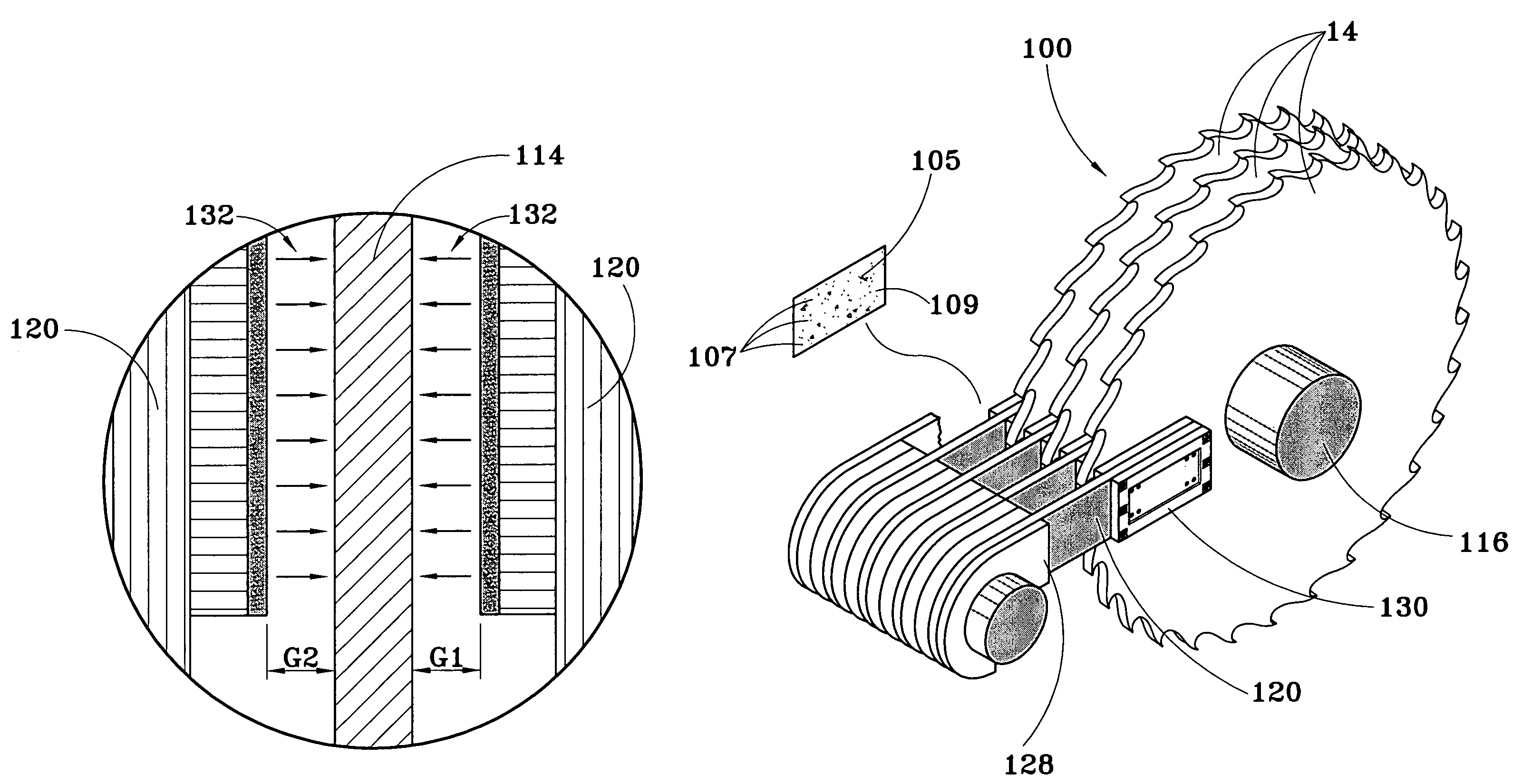
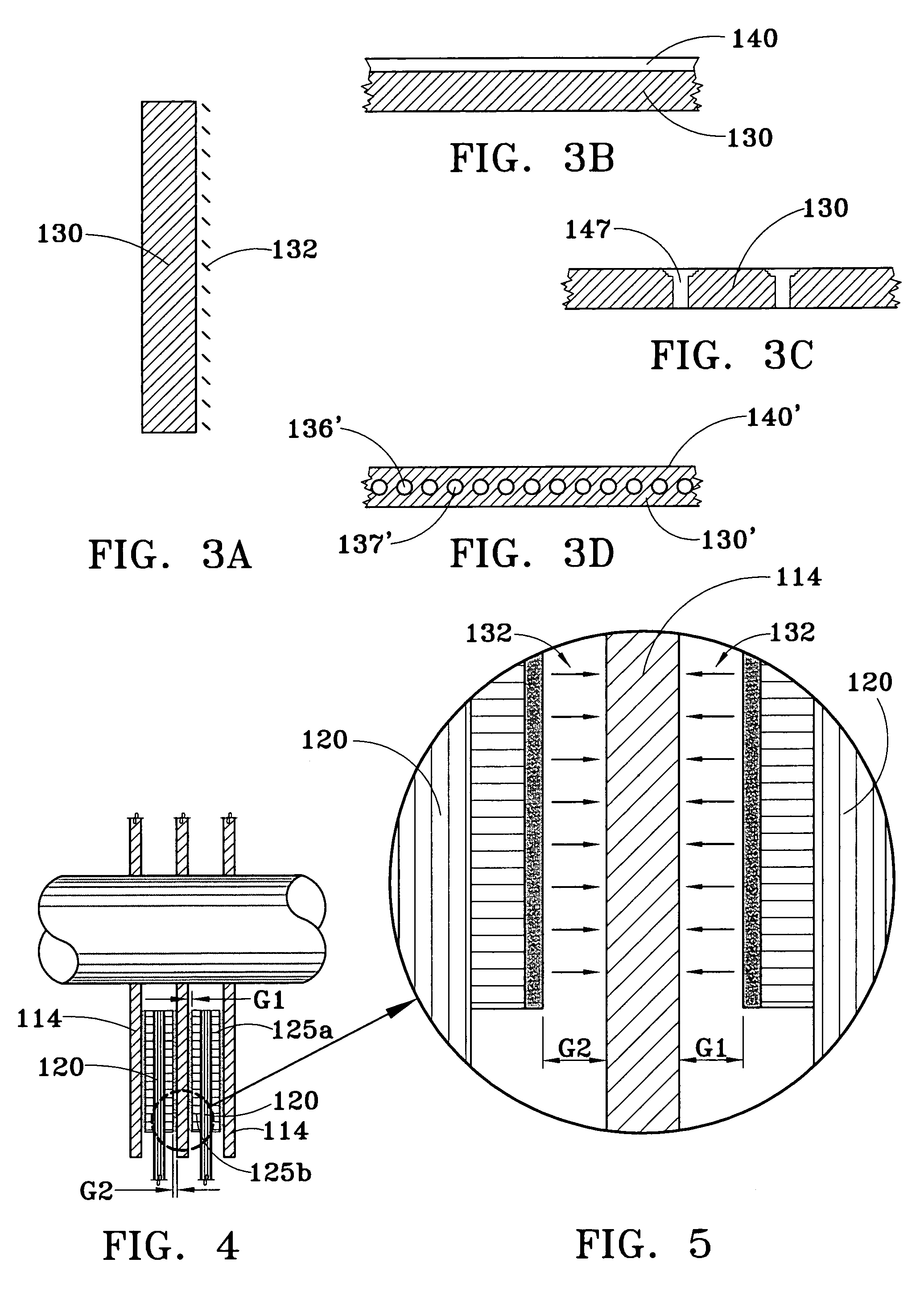
[0014]In view of the above, it is an object of the present invention to combine a saw guide block assembly with a magnetically-padded bearing surface and a fluid with ferromagnetic particles to create a magnetic, regenerating sacrificial film that significantly increases the overall durability of the guide block assembly and maintains the integrity thereof.
[0017]In view of the above, a feature of the present invention is to provide a multi-blade system and improved guide block assembly that is relatively simple structurally.

Problems solved by technology

However, the current systems, operating under current conditions, do not generate enough heat to allow extreme pressure lubricant additives such as chlorine or sulfur to effectively minimize the effects of blade and bearing guide impacts through low surface friction metal salt formation.
Furthermore, any metal salt formation on the surface of the bearing guide is dependent on the surface height of the remaining metal, which will precipitously decrease as wear occurs and does not effectively address the problem.
In addition, the impacts that do occur degrade the ability of the guide block to keep the axially opposed saw blades on plane and cutting properly.

Method used


Image

  • Multiple-blade saw system with magnetic bearing guide blocks and ferromagnetic lubricant, coolant and coating system
  • Multiple-blade saw system with magnetic bearing guide blocks and ferromagnetic lubricant, coolant and coating system
  • Multiple-blade saw system with magnetic bearing guide blocks and ferromagnetic lubricant, coolant and coating system

Examples


Embodiment Construction

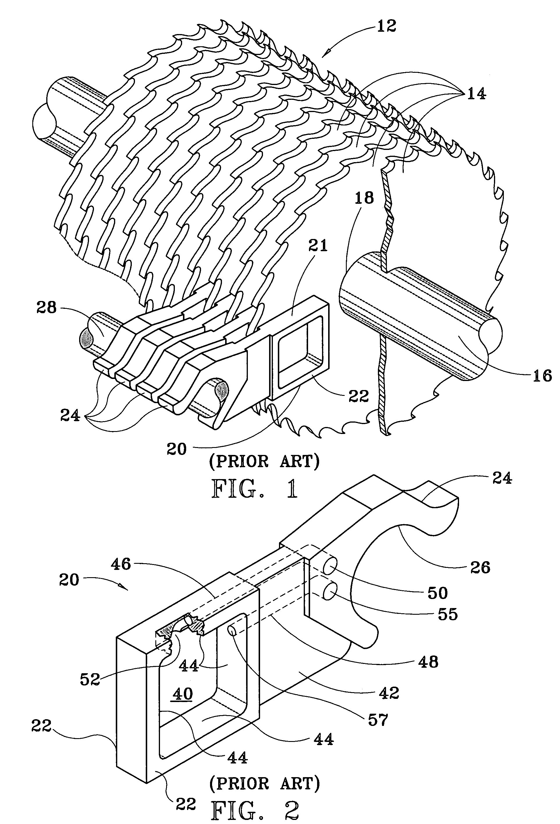
[0031]Referring now to FIGS. 1 and 2, and specific reference to U.S. Pat. No. 4,848,200, as is well known in the prior art a multiple blade saw assembly 12 has a plurality of individual saw blades 14 mounted on a common drive shaft 16 and axially spaced therealong. The outer surface of the drive shaft 16 includes axially aligned serrations which engage a similar pattern of serrations in the central hole 18 of the saw blade 14.

[0032]Individual guide blocks 20 have bearing blocks 21 which are positioned between adjacent saw blades 14. Moreover, each bearing block 21 includes a pair of bearing surfaces 22 lying immediately adjacent to the face of adjacent saw blades 14. The clearance between the bearing surfaces 22 of the bearing blocks 21 and the saw blades 14 is generally in the range of 0.001 to 0.004 inches. The bearing surfaces 22 are made of a low friction material in order to reduce heat generation as the blades are rotated.

[0033]Each saw guide block 20 includes a mounting brack...


PUM

PropertyMeasurementUnit
Magnetic fieldaaaaaaaaaa
Areaaaaaaaaaaa
Hardnessaaaaaaaaaa

Abstract

Improved saw guide block and fluid for a multiple blade saw assembly. Individual guide blocks are disposed between adjacent saw blades, which blades are mounted on a common drive shaft and axially spaced. Each of the guide blocks has a pair of oppositely-directed block pads that create a magnetically-padded bearing surface. Each block pad includes magnetic portions and non magnetic portions. Each non magnetic portion has fluid delivery ports to allow the transport of ferromagnetic, lubricant, coolant, coating fluid to the magnetically-padded bearing surfaces. The magnetic portion forms a magnetic field of attraction in its vicinity for capture and adherence of ferromagnetic particles within the fluid, whereby a magnetic coating on the guide block bearings surfaces is continuously regenerated during operation of the saw assembly.

Description

BACKGROUND OF THE INVENTION[0001]1. Field of the Invention[0002]The present invention relates to multiple-blade saw systems with saw guide lubricating systems and, more particularly, to a multiple-blade saw system having a magnetic bearing guide surface and a ferromagnetic lubricant, coolant and coating fluid which allows for continuous regeneration of the saw bearing guide surface with ferromagnetic particles.[0003]2. General Background[0004]Multiple blade saw systems used in the lumber industry use very thin circular saw blades which tend to warp and deform during use. Therefore, mechanisms have been deployed to prevent warping and deformation of the blades. It is common for guiding systems to use large babbitt saw guide blocks which typically require large amounts of cooling water to cool both the saw blades and saw guide blocks while the saws are cutting.[0005]Under the current operating conditions, temperature is controlled through the introduction of cooling fluids to the blad...

Claims


Application Information

Patent Timeline
IPC IPC(8): B26D5/00
CPCB23D47/02B27B5/34B23D59/02Y10T83/8878Y10T83/7264Y10T83/869Y10T83/263Y10T83/8881
Inventor TEGEN, MARK G.
Owner TEGEN MARK G
Learn More