Optical recording medium recorded with information in depth direction, and method and apparatus of reproduction therefrom
a technology of optical recording medium and depth direction, applied in the field of optical recording medium, can solve the problems of reducing the region where user data can be recorded on the disk, reducing the region where user data can be written on the disk, and not being desirable, so as to increase the lead-in region, increase the capacity of the lead-in region, and ensure the effect of sufficient us
- Summary
- Abstract
- Description
- Claims
- Application Information
AI Technical Summary
Benefits of technology
Problems solved by technology
Method used
Image
Examples
first embodiment
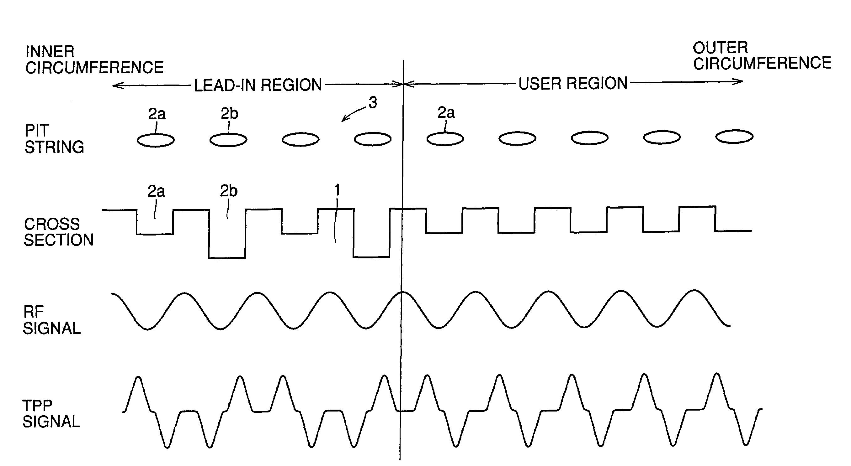
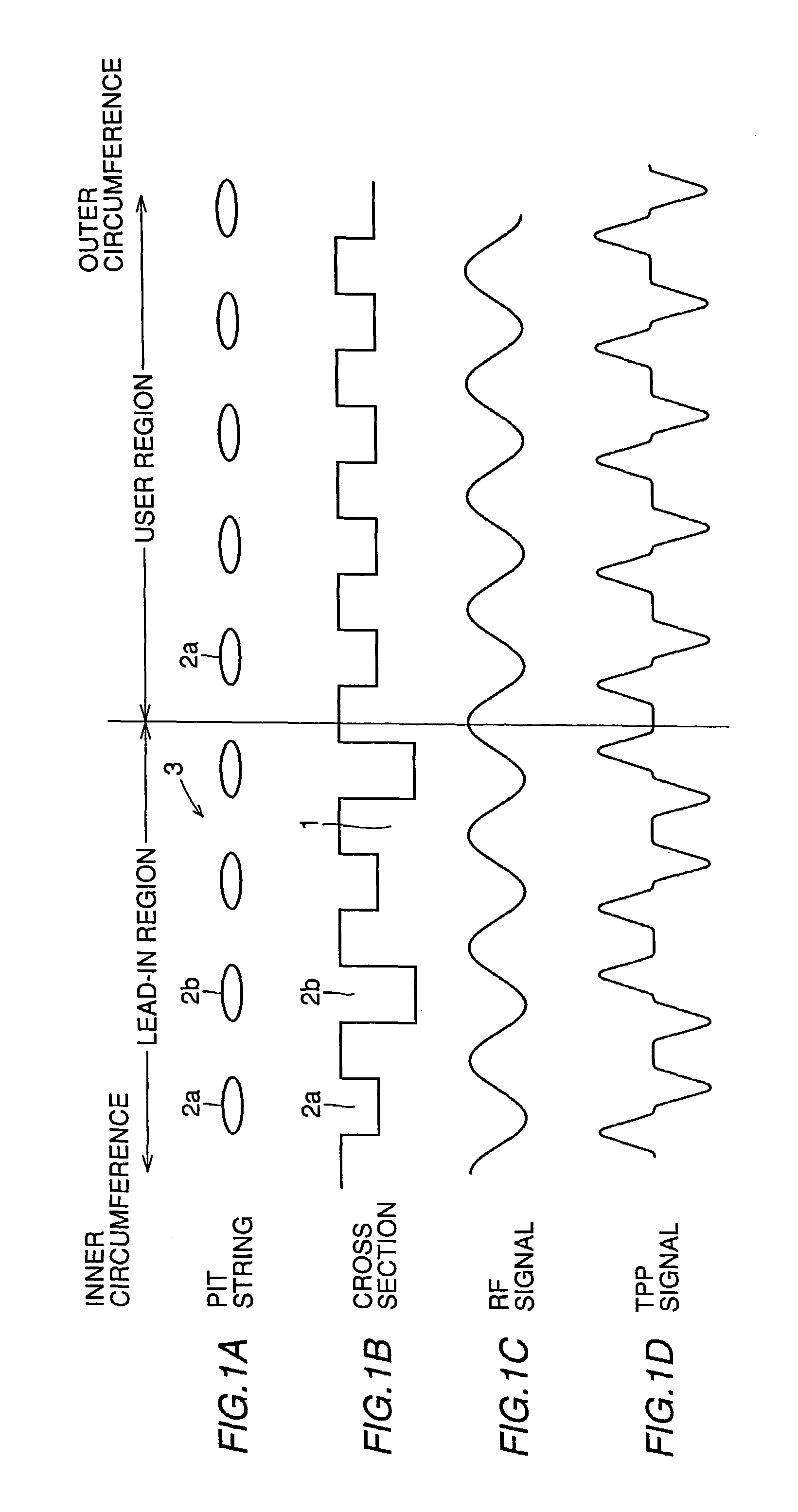
[0085]An optical recording medium and a reproduction method and apparatus thereof according to a first embodiment of the present invention will be described hereinafter. FIGS. 1A and 1B schematically show a structure of a pit string on a ROM disk as an example of an optical recording medium in the first embodiment. FIGS. 1C and 1D represent the waveforms of signals obtained by reproducing information from the ROM disk.
[0086]More specifically, FIG. 1A schematically shows pit string 3 constituted by two types of pits 2a and 2b, illustrated in a linear version from the inner circumference region to the outer circumference region of the disk. FIG. 1B schematically shows the cross section of the disk, corresponding to pit string 3 of FIG. 1A. Referring to FIG. 1B, the lead-in region is formed of relatively shallow pits 2a (depth D1) and relatively deep pits 2b (depth D2). The user region is formed of pits 2a of a constant depth (depth D1). FIG. 1C shows an RF signal representing the quan...
second embodiment
[0105]Referring to FIG. 4, an identify circuit of recorded information in a reproduction apparatus of an optical recording medium according to a second embodiment of the present invention will be described with reference to FIG. 4. More particularly, FIG. 4 is a block diagram showing the circuit configuration that allows detection of the presence of pits from which a TPP signal of different polarity can be obtained on the optical disk.
[0106]Similar to the reproduction apparatus of the first embodiment shown in FIG. 2, the outputs from regions A and B of detector 6 are provided to differential amplifier 7 and addition amplifier 8. Similar to the first embodiment of FIG. 2, the TPP signal which is the output of differential amplifier 7 is applied to comparators 9 and 10. The TPP signals binarized by respective comparators 9 and 10 are applied to a marker detection circuit 15. The RF signal which is the output of addition amplifier 8 is provided to comparator 14 to be compared with a p...
third embodiment
[0109]A recordable disk as an example of an optical recording medium according to a third embodiment of the present invention will be described here with reference to FIGS. 5A-5D. FIGS. 5A and 5B schematically show the structure of a mark string and pit string on a recordable disk according to the third embodiment. FIGS. 5C and 5D represent the waveforms of signals obtained by reproducing the information recorded on the disk.
[0110]In general, mark 25 is written in either or both of the groove and land. The third embodiment of FIG. 5 corresponds to the example where marks 25 are written in groove 24.
[0111]More specifically, FIG. 5A schematically shows mark strings 26 constituted by marks 25 formed in groove 24 and a pit string 23 constituted by pits 22a and 22b arranged between these mark strings, illustrated in a linear version from the inner circumference region to the outer circumference region of the disk. FIG. 5B schematically shows the cross section of the disk corresponding to...
PUM
| Property | Measurement | Unit |
|---|---|---|
| contrast | aaaaa | aaaaa |
| contrast | aaaaa | aaaaa |
| wavelength | aaaaa | aaaaa |
Abstract
Description
Claims
Application Information
 - R&D
- Intellectual Property
- Life Sciences
- Materials
- Tech Scout
- Unparalleled Data Quality
- Higher Quality Content
- 60% Fewer Hallucinations
Browse by: Latest US Patents, China's latest patents, Technical Efficacy Thesaurus, Application Domain, Technology Topic, Popular Technical Reports.
© 2025 PatSnap. All rights reserved.Legal|Privacy policy|Modern Slavery Act Transparency Statement|Sitemap|About US| Contact US: help@patsnap.com


