
Low loss lateral optical waveguide intersections

a technology of lateral optical waveguides and intersections, which is applied in the direction of optical waveguide light guides, instruments, optics, etc., can solve the problems of more difficult to achieve low crosstalk and the design of ideal waveguide crossings in conventional devices, and achieves the effects of reducing transmission loss, minimizing diffraction, and minimizing transmission loss

Inactive Publication Date: 2009-08-18
INFINERA CORP
View PDF6 Cites 6 Cited by
  • Summary
  • Abstract
  • Description
  • Claims
  • Application Information

AI Technical Summary

Benefits of technology

This approach reduces transmission loss by a factor of 10, effectively eliminating crosstalk and improving power transmission efficiency, while maintaining a simple and efficient waveguide crossing design.

Problems solved by technology

Ideal waveguide crossing design in conventional devices has been a matter of trial and error.
High losses associated with bends in conventional waveguides, along with the resulting transmission loss, as seen in untapered perpendicular intersections, has forced conventional designers to create shallow-angle crossings that make it even more difficult to achieve low crosstalk.

Method used


Image

  • Low loss lateral optical waveguide intersections
  • Low loss lateral optical waveguide intersections
  • Low loss lateral optical waveguide intersections

Examples


Embodiment Construction

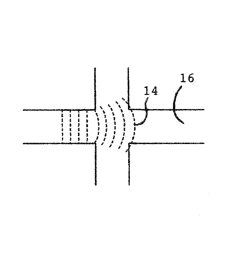
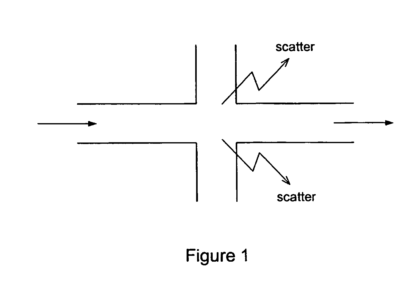
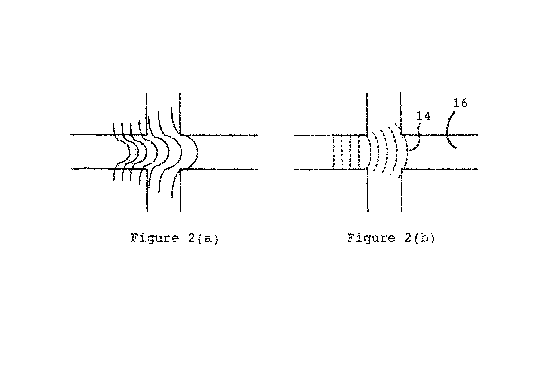
[0036]The invention comprises a low loss lateral waveguide intersection. This invention minimizes the focus on optical field distortions resulting from the influence of interfering fields from an adjacent or lateral waveguide having perpendicular intersections. Such a lateral and perpendicular intersection allows for two waveguides crossing in a precise geometric pattern. Three waveguides could potentially intersect perpendicularly in a three-dimensional waveguide crossing. A major feature of the inventive concept is that it reduces transmission loss due to diffractive scattering of light in the intersecting region illustrated in FIG. 1. Transmission loss results from the diffraction of the optical field in the intersecting region where the field is no longer bound by the waveguide geometry. FIG. 2(a) shows the diffraction of the amplitude as the field of light expands in the intersecting region. This expanding field causes the phase front to be parabolically curved, as depicted in ...


PUM


Abstract

A geometrically shaped optical waveguide crossing or intersection with minimal transmission loss is described. A symmetrically tapered waveguide intersection is used to minimize loss in the intersecting region where at least two optical waveguides cross one another at 90° or nearly 90°. The present invention embodies a waveguide crossing that includes tapering the width of the waveguides as they approach the intersecting region, forcing the propagating light to contract, thereby reducing asymmetric field distortions, and thus reducing transmission loss and effectively minimizing crosstalk. This is accomplished by focusing the propagating light through a perpendicular or near perpendicular in at least two waveguide intersection by simple linear tapering rather than by the use of a lens or other previously used devices.

Description

REFERENCE TO RELATED APPLICATION[0001]This patent application is the national stage of international application, Serial No. PCT / US02 / 33881, filed Oct. 23, 2002 and specifically incorporates and claims priority of provisional patent application Ser. No. 60 / 343,709 filed at the United States Patent and Trademark Office on Oct. 26, 2001.BACKGROUND OF THE INVENTION[0002]1. Field of the Invention[0003]This invention relates to intersecting optical waveguides with reduced transmission loss. In high-density integrated optical circuits, waveguide crossings are inevitable. One characteristic that results from intersecting waveguide crossings is an intersecting region where light entering is no longer bound by the waveguide geometry. Light in an unbound intersecting region, analogous to a freely expanding wave without boundaries, freely expands and its phase front becomes parabolically curved to the point that the other side of the intersection can no longer collect the entire field of the e...

Claims


Application Information

Patent Timeline
Patent Type & Authority Patents(United States)
IPC IPC(8): G02B6/12G02B6/28
CPCG02B6/2804G02B2006/1215
Inventor LITTLE, BRENT E.
Owner INFINERA CORP
Learn More