
Packet transmission method and system, base station, wireless LAN terminal, and wireless LAN system using the same

a packet transmission and wireless technology, applied in multiplex communication, data switching networks, wireless commuication services, etc., can solve the problems of inability to efficiently transmit packets, inability to utilize original transmission rates, and inability to achieve real-time communication

Active Publication Date: 2009-08-18
NEC CORP
View PDF23 Cites 11 Cited by
  • Summary
  • Abstract
  • Description
  • Claims
  • Application Information

AI Technical Summary

Benefits of technology

[0015]According to a still further aspect of the present invention, there is provided a wireless LAN system comprising the above base station equipment, the above wireless LAN terminal equipment connected to the base station equipment via a wireless LAN, and arbitrating means for transmitting delay request information for delaying transmission of packets from the base station equipment to the wireless LAN terminal equipment such that the packet transmission does not overlap with other terminals thereby to arbitrate transmission of packets from the wireless LAN terminal equipment to the base station equipment so as not to cause a collision thereof.
[0020]According to a still further aspect of the present invention, there is provided a wireless LAN system comprising the above base station equipment, the above wireless LAN terminal equipment connected to the base station equipment via a wireless LAN, arithmetic means for computing use efficiency of a general queue for accumulating general packets other than prioritized capsules, using a predetermined arithmetic expression, and control means for changing coefficients of the arithmetic expression according to the state of accumulation of the general queue to thereby control the value of the use efficiency computed by the arithmetic means.

Problems solved by technology

However, the real time communication such as the VoIP via the conventional wireless LAN had the following problems.
That is, since the wireless LAN headers were large and the RTP packets were of short packets, the original transmission rate could not be utilized.
Since there was no matching between communication timing of the wireless LAN and the period of a CODEC, the efficient transmission of packets could not be carried out.

Method used


Image

  • Packet transmission method and system, base station, wireless LAN terminal, and wireless LAN system using the same
  • Packet transmission method and system, base station, wireless LAN terminal, and wireless LAN system using the same
  • Packet transmission method and system, base station, wireless LAN terminal, and wireless LAN system using the same

Examples


first embodiment

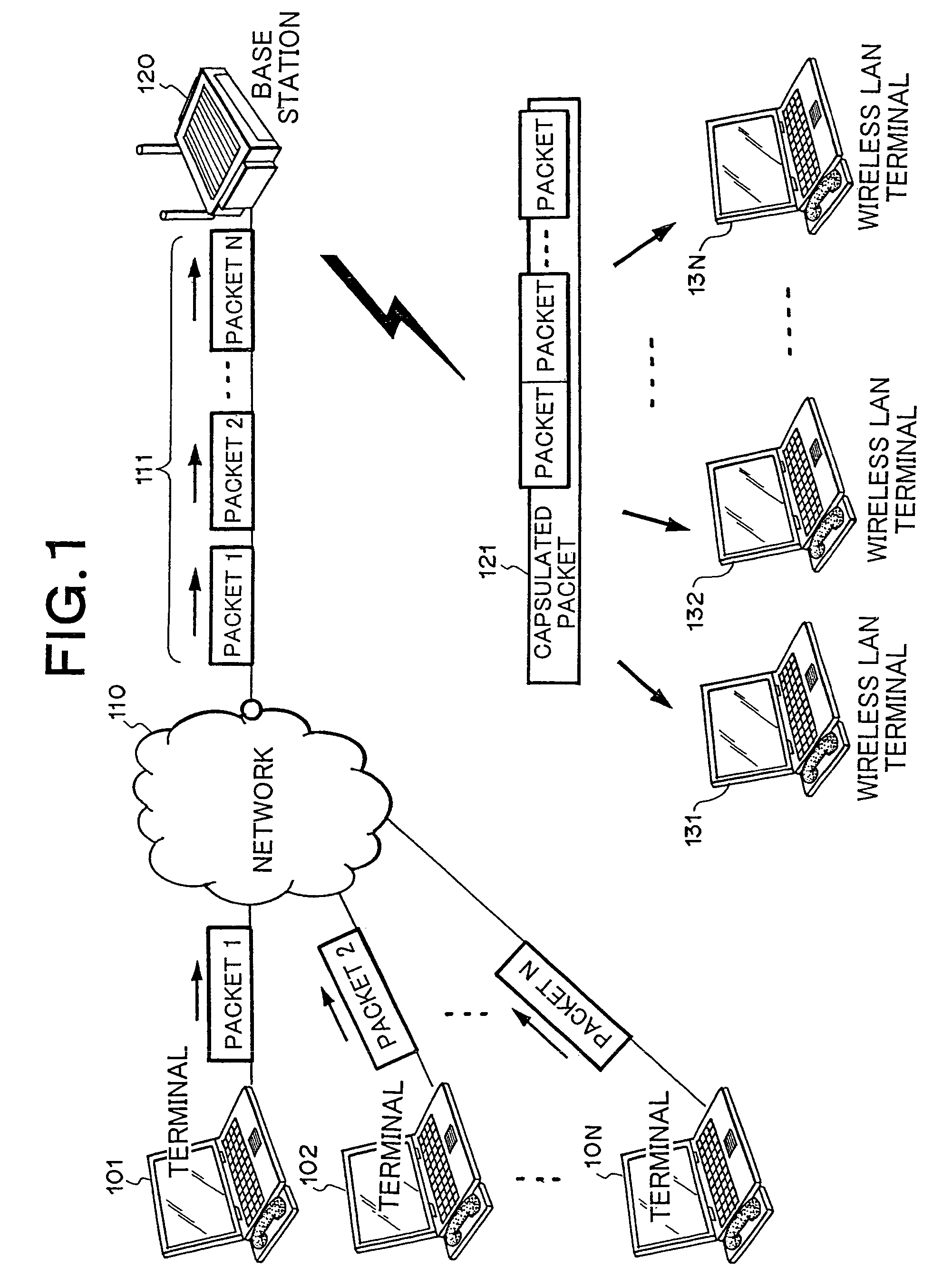
[0037]FIG. 1 is a block diagram showing a first embodiment of the present invention. In FIG. 1, terminals 101, 102, . . . , 10N respectively have CODECs and network interfaces and transmit and receive packets 1, 2, . . . , N for data communication and real time communication. A network 110 comprises Internet or a LAN or the like, which is capable of IP communication and transmits RTP packets and general packets.

[0038]Packets 111 (packets 1, 2, . . . , N) are RTP packets transmitted from the terminals 101, 102, . . . , 10N and transfer media data such as voice, moving pictures to individual destinations. A base station 120 includes QoS queues (refer to a subsequent description) that accumulate the packets 111 (RTP packets) transmitted from the network 110 and process the same on a priority basis, and an interval timer (refer to a subsequent description) that counts a period T obtained in the following expression (1) with respect to the period C of the CODEC used for generation of RTP...

second embodiment

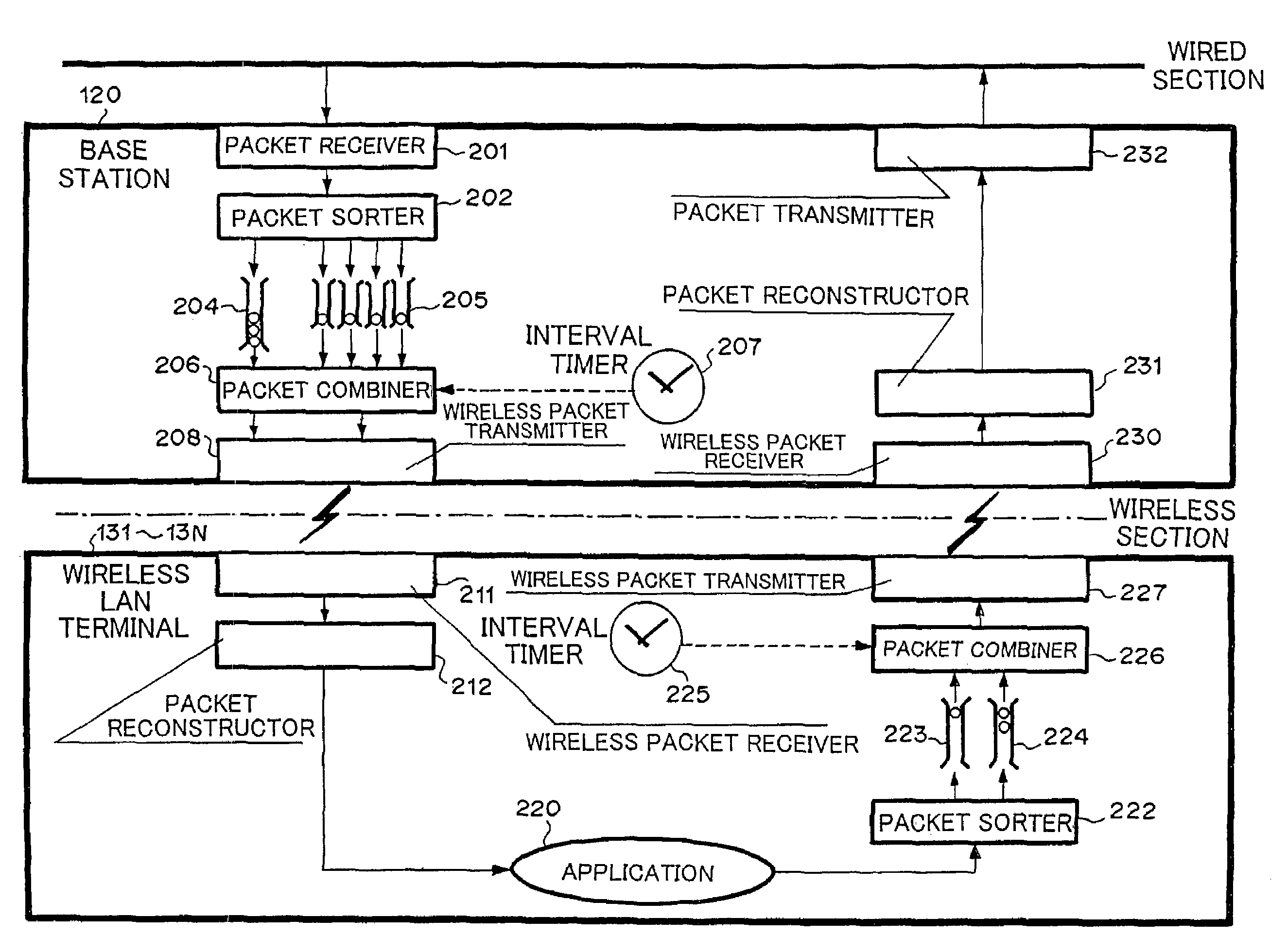
[0066]A second embodiment of the present invention will next be explained. The present embodiment is designed so as not to cause trouble in real time communication even when overload is imposed on packet transmission. Incidentally, the present embodiment is similar to FIGS. 1 and 2 illustrative of the first embodiment in respect to a system configuration and configurations of a base station and wireless LAN terminals.

[0067]In the present embodiment, packet sorters 202 and 222 respectively set queues every MAC addresses as to general queues 204 and 224 as shown in FIG. 5. Thus, since the general queues 204 and 224 are queued every MAC addresses, there is no harm in transmitting packets even if the packet transmission to other terminals is congested.

third embodiment

[0068]A third embodiment of the present invention will next be explained. Although a system configuration and basic configurations of a base station and wireless LAN terminals in the third embodiment are similar to FIGS. 1 and 2 illustrative of the first embodiment, the third embodiment is further contriving the transmission of packets from the wireless LAN terminals to the base station. FIG. 6 shows a timing chart thereof.

[0069]In FIG. 6, an interval timer 300 of a base station 120 counts the period T taken to transmit a capsulated packet from the base station 120 to wireless LAN terminals 131, 132, . . . , 13N. Interval timers 301, 302, . . . , 30N of the wireless LAN terminals 131, 132, . . . , 13N respectively counts timings provided to transmit capsulated packets from the wireless LAN terminals 131, 132, . . . , 13N to the base station 120.

[0070]A broadcast capsulated packet 310 from the base station 120 to the wireless LAN terminals 131, 132, . . . , 13N is packaged with packe...


PUM


Abstract

Disclosed herein is a packet transmission method wherein received packets are sorted into prioritized QoS packets and general packets other than the prioritized QoS packets, the sorted prioritized QoS packets are accumulated, the accumulated QoS packets are capsulated and then transmitted as a capsulated packet, and the capsulated packet is transmitted in matching with the period of a CODEC. In the preferred embodiment, there is provided a wireless LAN system comprising a base station and at least one wireless LAN terminal connected to said base station via a wireless LAN; and a packet transmission system for transmitting a packet between said base station and said at least one wireless LAN terminal via the wireless LAN, the packet transmission system. In the packet transmission system, a packet sorter sorts received packet into prioritized packets and packets other than the prioritized packets. A FIFO queue buffer (QoS queue) accumulates the sorted prioritized packets. A packet combiner capsulates the accumulated packets in the QoS queue. A wireless packet transmitter transmits the capsulated packet between the base station and the at least one wireless LAN.

Description

BACKGROUND OF THE INVENTION[0001]1. Field of the Invention[0002]The present invention relates to a packet transmission method and system for transmitting received packets, and a base station, a wireless LAN (Local Area Network) terminal, and a wireless LAN system using the same.[0003]2. Description of the Related Art[0004]FIG. 14 is a block diagram showing a configuration of a wireless LAN system according to a prior art example. Real time communication such as VoIP (Voice on Internet Protocol) via a conventional wireless LAN will be explained with reference to FIG. 14. In FIG. 14, terminals 1301, 1302, . . . , 130N respectively have a CODEC (COder-DECoder) and a network interface for transmitting and receiving packets 1, 2, . . . , N for data communication and real time communication. A network 1310 consists of Internet or a LAN or the like capable of IP (Internet Protocol) communication and transmits data packets and RTP (Real Time Protocol) packets.[0005]Packets 1311 (packets 1, ...

Claims


Application Information

Patent Timeline
Patent Type & Authority Patents(United States)
IPC IPC(8): H04W4/00H04B1/38H04J3/24H04L12/28H04W74/04H04L47/43H04L47/6275H04W28/00H04W28/02H04W28/14H04W72/12H04W84/12H04W92/10
CPCH04L12/5693H04L47/2416H04W72/1242H04L65/607H04L65/608H04L65/80H04L69/04H04L67/322H04L67/04H04L29/06H04L69/329H04L29/06027H04L2212/0025H04W28/065H04W28/14H04W72/1236H04W84/12H04L2212/00H04L47/50H04L65/70H04L65/65H04L67/61H04W72/543H04W72/569H04L9/40H04L65/1101
Inventor HASHIMOTO, NAOKIKOBAYASHI, YOSHIKAZU
Owner NEC CORP
Learn More