
Microfluidic device

a microfluidic device and microfluidic technology, applied in the field of microfluidic devices, can solve the problems of particularly undesirable dead volumes, junctions containing microfluidic conduits, and the existence of dead volumes is a recognized problem

Active Publication Date: 2009-08-18
SCIEX +1
View PDF8 Cites 54 Cited by
  • Summary
  • Abstract
  • Description
  • Claims
  • Application Information

AI Technical Summary

Benefits of technology

"The present invention provides a system and method for reducing the negative effects of a dead volume in a microfluidic conduit system. This is achieved by adding a drain conduit from the dead volume. The technical effect is improved liquid flow and reduced pressure drop in the system."

Problems solved by technology

The existence of dead volumes is a recognized problem in systems comprising microfluidic devices.
Dead volumes are particularly undesirable in analytical apparatus, because they cause dispersion in samples derived from, or directed to, liquid chromatography columns, and disturb the distribution of particles in samples to be examined in cytometry and like procedures.
The making of junctions comprising microfluidic conduits (for example junctions between a microfluidic conduit and a conventional elongate component, e.g. a capillary tube, optical fiber or electrical lead) presents many problems.

Method used


Image

  • Microfluidic device
  • Microfluidic device

Examples


Embodiment Construction

[0017]In the Summary of the Invention above, the Detailed Description of the Invention, the Examples, and the Claims below, and the accompanying drawings, reference is made to particular features of the invention, such features including for example aspects, components, ingredients, devices, apparatus, systems, steps and embodiments. It is to be understood that the disclosure of the invention in this specification includes all possible combinations of such particular features. For example, where a particular feature is disclosed in the context of a particular aspect, a particular embodiment, a particular Figure, or a particular claim, that feature can also be used, to the extent possible, in the context of other particular aspects, embodiments, Figures and claims, and in the invention generally. The invention claimed herein includes the use of features which are not specifically described herein but which provide functions which are the same as, equivalent to, or similar to, feature...


PUM

PropertyMeasurementUnit
equivalent diameteraaaaaaaaaa
diameteraaaaaaaaaa
equivalent diameteraaaaaaaaaa

Abstract

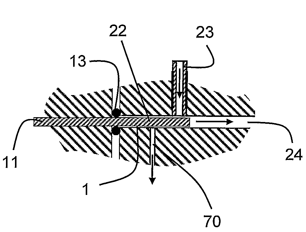
Microfluidic systems including a principal microfluidic conduit (24), an adjacent dead volume (1) and a drain conduit (70) which mitigates the adverse effects of the dead volume on the operation of the system.

Description

CROSS-REFERENCE TO RELATED APPLICATIONS[0001]This application claims priority from Provisional Application No. 60 / 559,383, entitled Improved Optical Detection Device, filed Apr. 2, 2004, the entire disclosure of which is incorporated herein by reference for all purposes.[0002]This application is related to (1) copending, commonly assigned U.S. patent application Ser. No. 10 / 410,313, filed Apr. 7, 2003 and issued on May 23, 2006 as U.S. Pat. No. 7,050,660, (2) PCT application PCT / US 04 / 10234, filed Apr. 2, 2004, by Eksigent Technologies LLC, claiming priority from Ser. No. 10 / 410,313, (3) copending, commonly assigned U.S. Provisional Application No. 60 / 559,140 filed Apr. 2, 2004, by Don Arnold et al. and entitled Microfluidic Connector and (4) the copending, commonly assigned International (PCT) application PCT / US05 / 11021, filed on Apr. 1, 2005 by Don Arnold et al. and entitled Microfluidic Connections. The disclosure of each of the above-identified applications is incorporated herei...

Claims


Application Information

Patent Timeline
Patent Type & Authority Patents(United States)
IPC IPC(8): B01L3/02G01N11/00B01L3/00B01L99/00B81B1/00
CPCB01L3/5027B01L3/502746B01L2200/0689B01L2300/0645B01L2300/0887B01L2300/0816B01L2300/0874B01L2300/0877B01L2300/0654Y10T137/8593
Inventor ARNOLD, DON W.
Owner SCIEX
Learn More