
Cable clamping electrical plug

a clamping and electrical plug technology, applied in the field of electrical plugs, can solve the problems of unsuitable repeated connection of plugs, large force and time, and easy loss of plugs, and achieve the effect of optimizing the amount of available space in the plug and quick and easy method of cable connection

Active Publication Date: 2009-08-11
TE CONNECTIVITY GERMANY GMBH
View PDF14 Cites 35 Cited by
  • Summary
  • Abstract
  • Description
  • Claims
  • Application Information

AI Technical Summary

Benefits of technology

The invention is an electrical plug that allows for easy and quick connection of cables while optimizing space. It consists of two rotatable housings with contact elements inside. There is a cable end seating between the two housings with a surface for each housing with a seating for a conductor element of the cable. The contact elements make electrical contact with the conductor elements when the housings are closed.

Problems solved by technology

However, these plugs have the disadvantage that they can only be connected to a cable at great cost in force and time.
Additionally, such plugs are unsuitable for repeated connection.
However, such separate parts have the disadvantage that they are easily lost.
A problem of the prior art described above is that it requires a lot of force and time to connect the multipole, i.e. eight-pole, plugs to the cable.

Method used


Image

  • Cable clamping electrical plug
  • Cable clamping electrical plug
  • Cable clamping electrical plug

Examples


Embodiment Construction

)

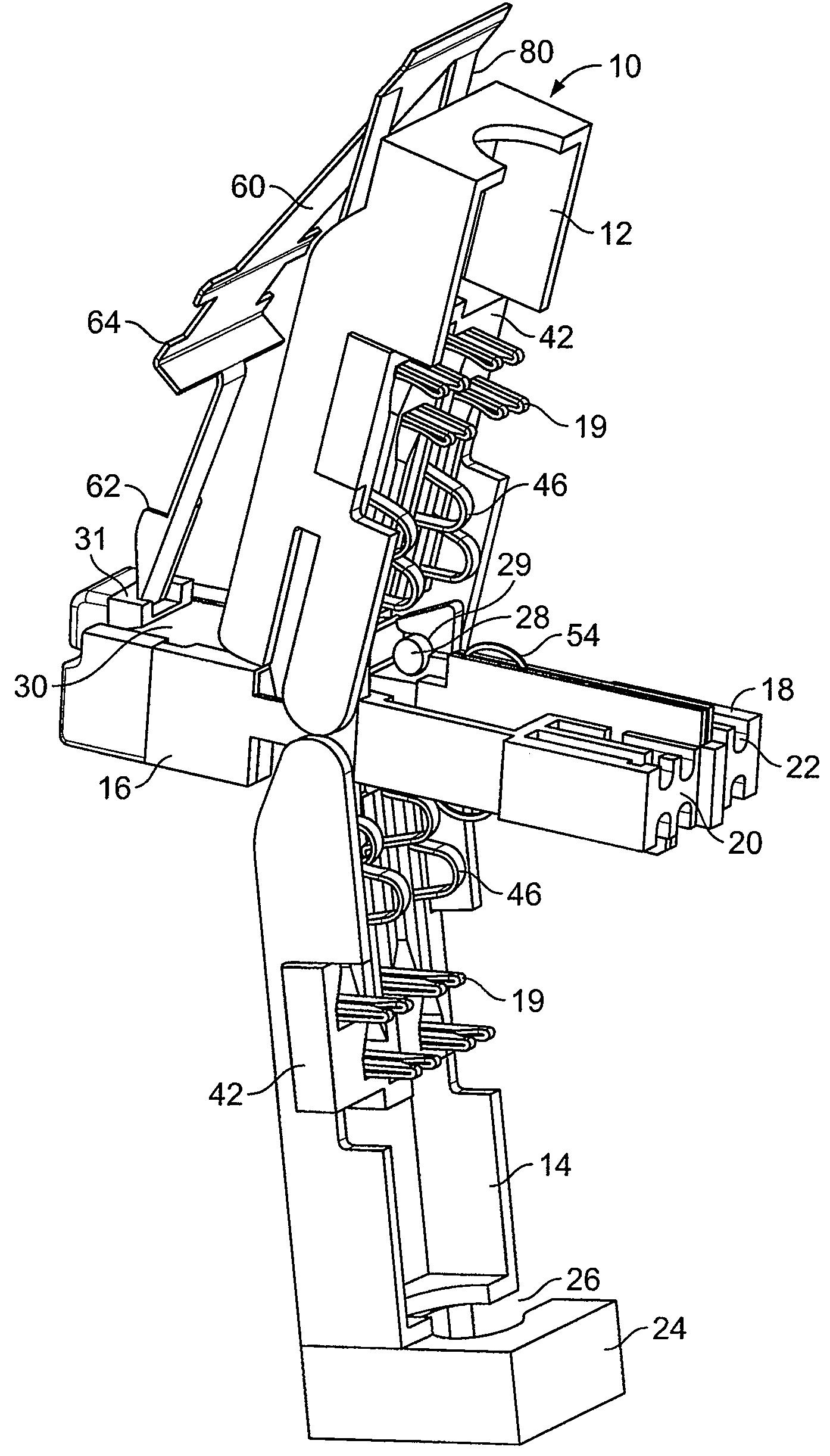
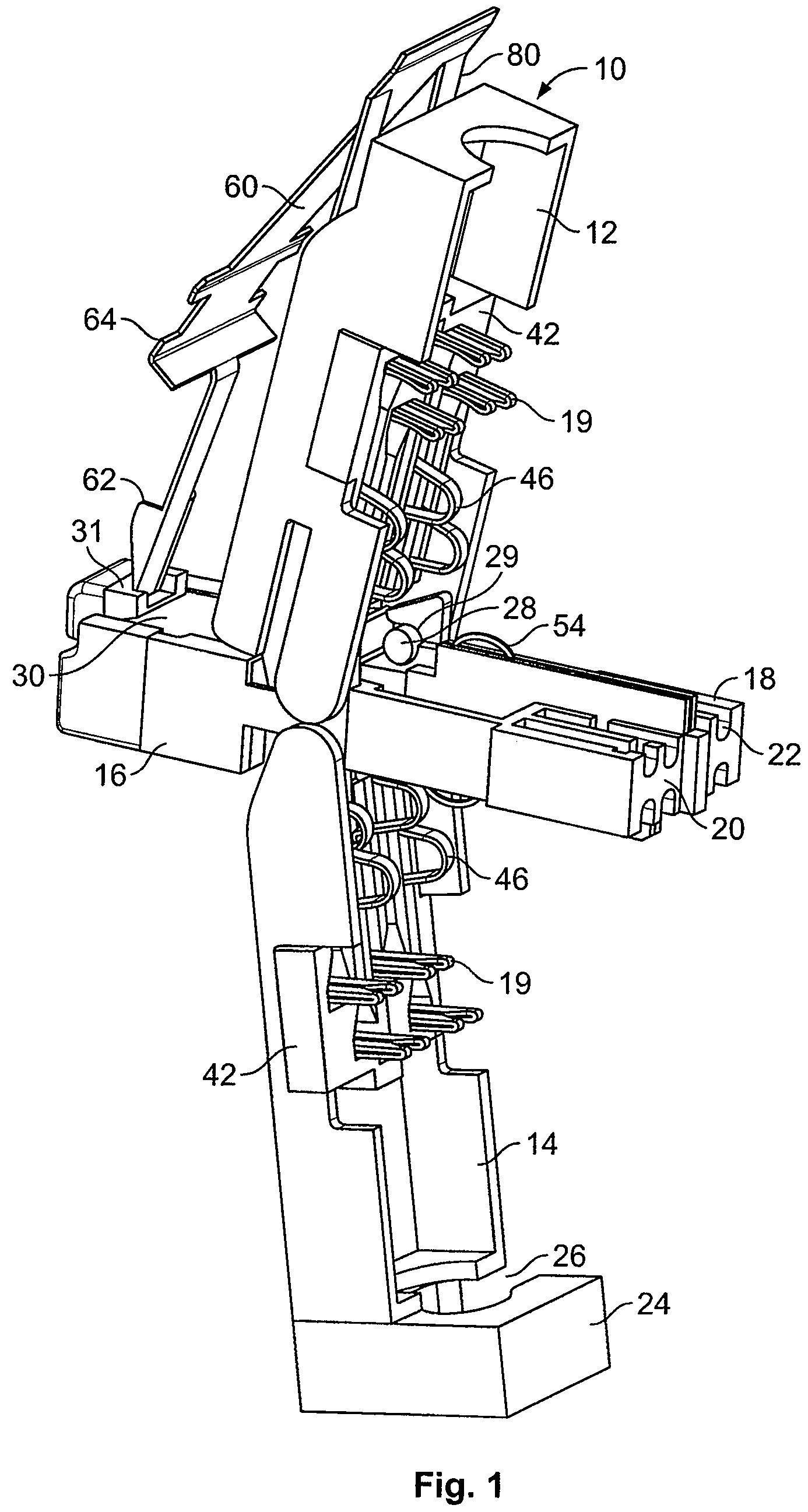
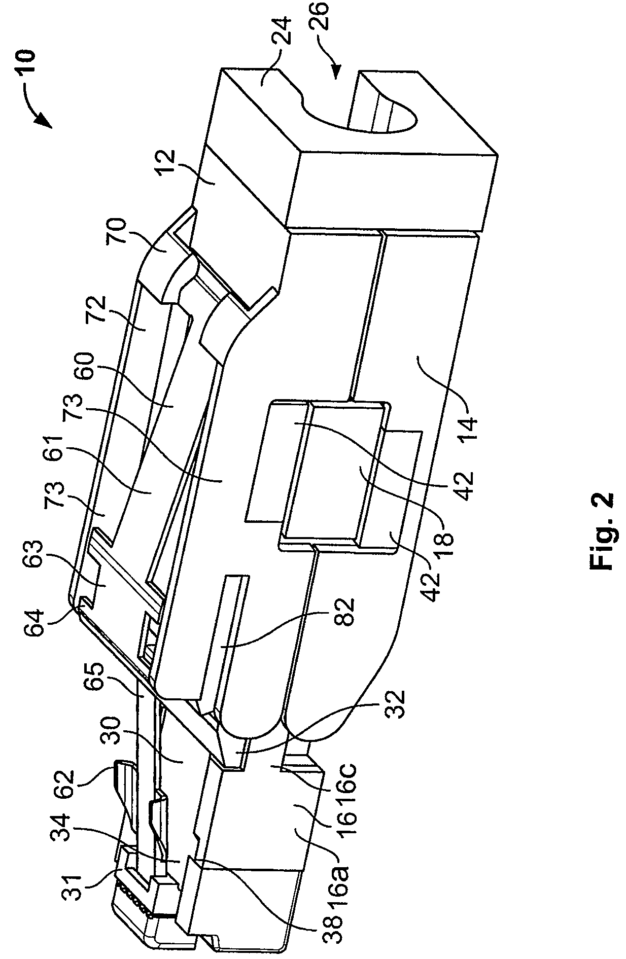
[0016]FIGS. 1-3 show a first embodiment of an electrical plug 10 according to the invention. As shown in FIG. 1, the plug 10 includes a first housing 12, a second housing 14, a third housing 16 and an insulation device 18. As shown in FIGS. 1 and 3, the first housing 12 is provided with a contact carrier 42 on an inside surface thereof. Contact elements 19 are provided in the contact carrier 42. The contact elements 19 have contact sections 46. The contact sections 46 may be formed, for example, as spring contacts. Journals or projections 28 extend from inside surfaces of opposing side walls of the first housing 12. The first housing 12 has seating sections 70 and a seating 72. The seating 72 is delimited by side walls 73. Grooves 82 are provided on the side walls 73. The grooves 82 are formed substantially parallel to a plugging direction in which the plug 10 is plugged into a plug seating (not shown).

[0017]As shown in FIGS. 1 and 3, the second housing 14 is connected to the first...


PUM


Abstract

An electrical plug comprises first and second housings rotatable between an open position and a closed position. The first and second housings each have contact elements arranged therein. A cable end seating is arranged between the first and second housings. The cable end seating has a first surface facing the first housing and an opposing second surface facing the second housing. The first and second surfaces are each provided with at least one seating for receiving a conductor element of a cable to be connected to the plug. The contact elements electrically contact the conductor elements when the first and second housings are in the closed position.

Description

CROSS-REFERENCE TO RELATED APPLICATIONS[0001]This application claims the benefit of the filing date under 35 U.S.C. § 119(a)-(d) of German Patent Application No. DE 10 2006 039 799.1, filed Aug. 24, 2006.FIELD OF THE INVENTION[0002]The invention relates to an electrical plug for connection to a plug seating wherein the plug includes first and second housings rotatable into engagement with a cable end seating arranged therebetween.BACKGROUND[0003]From the prior art, traditional 8-pole RJ-45 plugs, which mostly consist of transparent plastic, are known. To fix a cable, individual conductors of the cable are pushed or plugged into a housing of the plug. Using a crimping tool, the cable is then pressed firmly onto the plug. However, these plugs have the disadvantage that they can only be connected to a cable at great cost in force and time. Additionally, such plugs are unsuitable for repeated connection. In the case of many plugs, a separate assembly slide is also used to insert the ind...

Claims


Application Information

Patent Timeline
Patent Type & Authority Patents(United States)
IPC IPC(8): H01R4/24H01R12/55
CPCH01R4/2433H01R13/6658H01R24/64
Inventor SZELAG, MARTINSCHMIDT, RALFBERGNER, BERTBOECK, WERNER
Owner TE CONNECTIVITY GERMANY GMBH
Learn More