Spring fastener having stabilizing barbs

a technology of spring fasteners and stabilizers, which is applied in the direction of sleeves, fastening means, cuffs, etc., can solve the problems of vibration noise, most annoying and often inacceptable levels, and the task of achieving such connection becomes very difficult, if not impossible, for all practical purposes, and the bolt loosening

Inactive Publication Date: 2009-08-11
EUSTATHIOS VASSILIOU ROVOCABLE TRUST U A D 12 25100
View PDF52 Cites 11 Cited by
  • Summary
  • Abstract
  • Description
  • Claims
  • Application Information

AI Technical Summary

Problems solved by technology

This arrangement presents many problems, among which, one of the most important is that in the case that one object is hollow, the nut has to be in place at the back of the hollow object before assembling the two objects together.
If for any reason the nut is misplaced, and / or if it becomes desirable to introduce a new fastening connection between the two objects, the task of achieving such connection becomes very difficult, if not impossible, for all practical purposes.
In addition, vibration during the operation of a device, such as an automobile or appliance for example, containing the two objects results very often in loosening of the bolt or “quick nut” and in either full disassembling of the objects from each other, or in a vibration noise which is most annoying and often of unacceptable levels.
Further, such connections are not water-resistant and water may be easily penetrate the connection point and be transferred from one side of one or both objects to the other side.
This impression derived funnel is rather inflexible and in some occasions has a tendency to drive the expanding member in undesired direction.
However, if the width of the slot in which the fastener is inserted is wider than the thickness of the body of the fastener under the head of said fastener, the fastener wobbles within the slot.
Similarly if the thickness of the substrate is thinner than necessary, a similar wobbling of the fastener occurs.
This is defective behavior of the fastener producing rattling noises among other deficiencies, and in many occasions it is completely unacceptable.

Method used


Image

  • Spring fastener having stabilizing barbs
  • Spring fastener having stabilizing barbs
  • Spring fastener having stabilizing barbs

Examples


Embodiment Construction

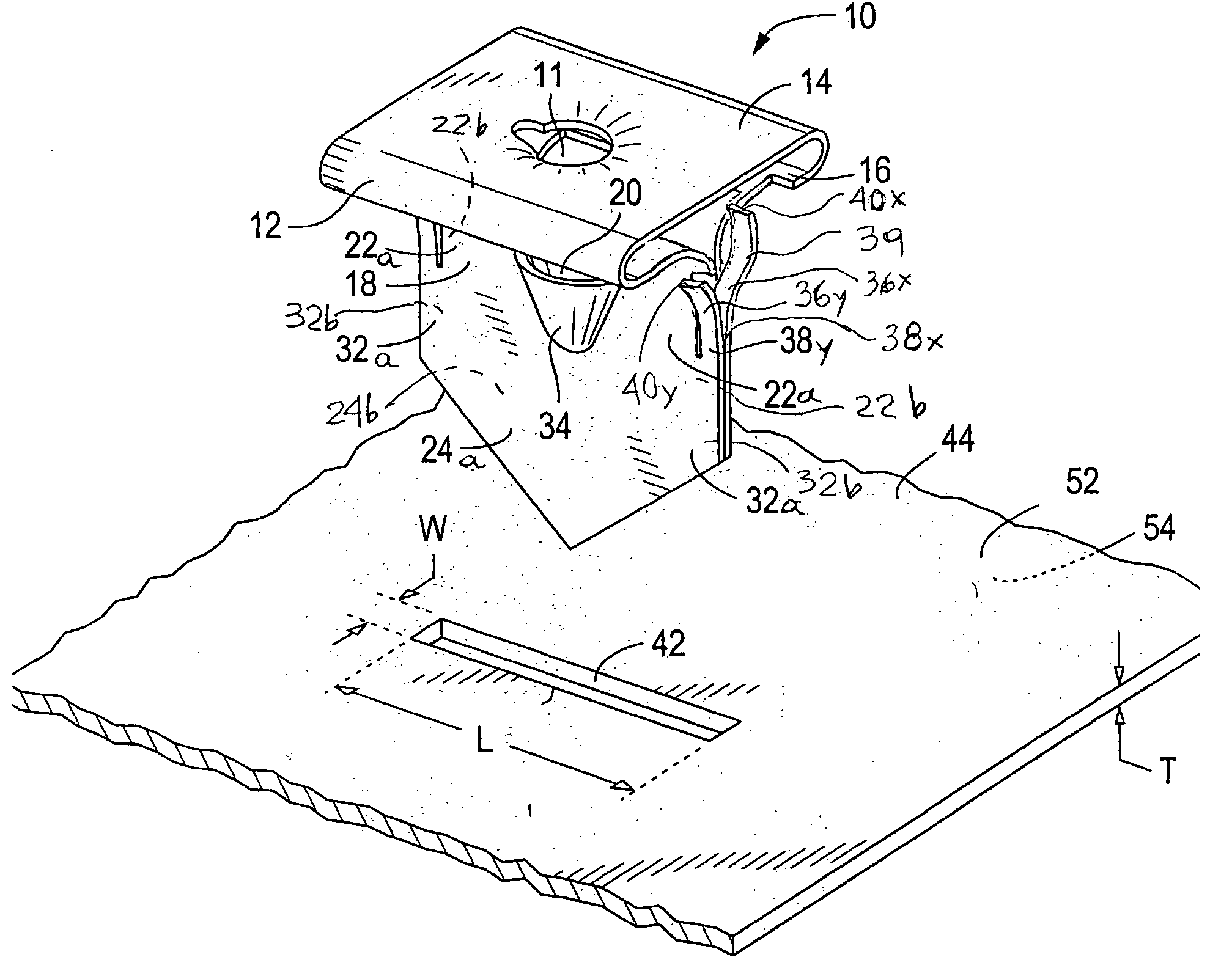
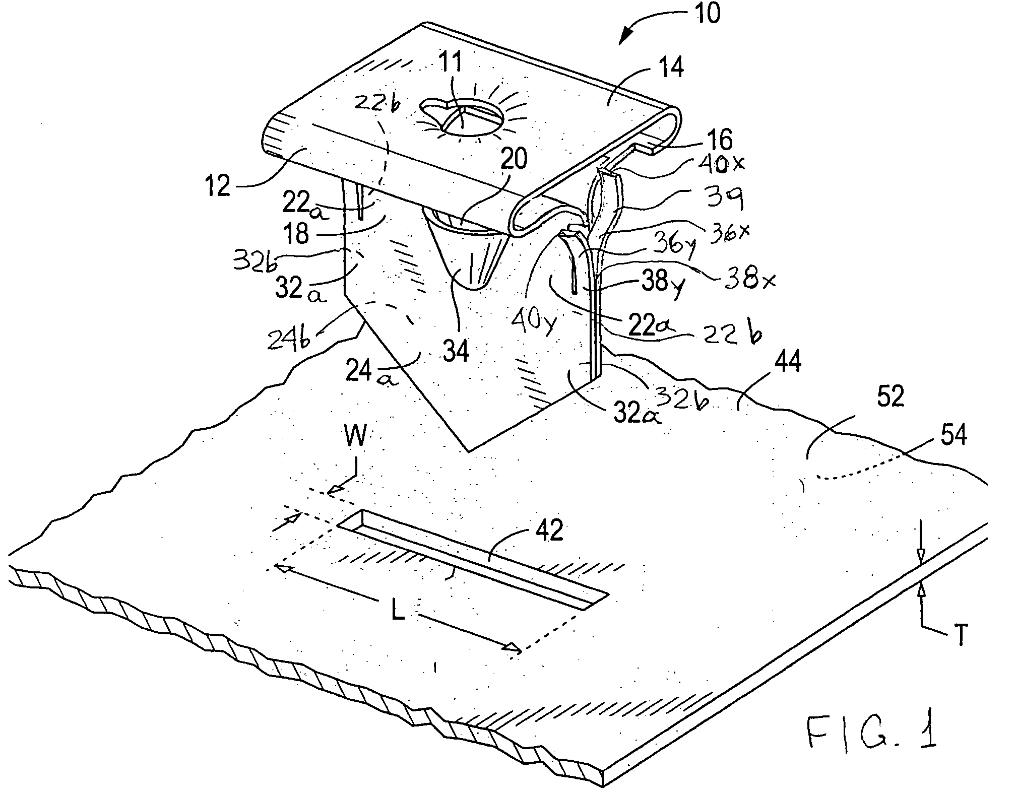
[0036]The fasteners of the type disclosed in U.S. Pat. No. 4,500,238 are intended for use mainly in hollow walls. Fasteners of the same type, which are used in industrial applications, wherein the fastener is first inserted into the slot of a sheet, usually a metal sheet, such as the frame of an automobile for example, have barbs which secure initially the fastener on the sheet. However, if the width of the slot in which the fastener is inserted is wider than the thickness of the body of the fastener under the head of said fastener, the fastener wobbles within the slot. Similarly if the thickness of the substrate is thinner than necessary, a similar wobbling of the fastener occurs. As aforementioned, this is defective behavior of the fastener since it results in rattling noises among other deficiencies, and in many occasions it is completely unacceptable.

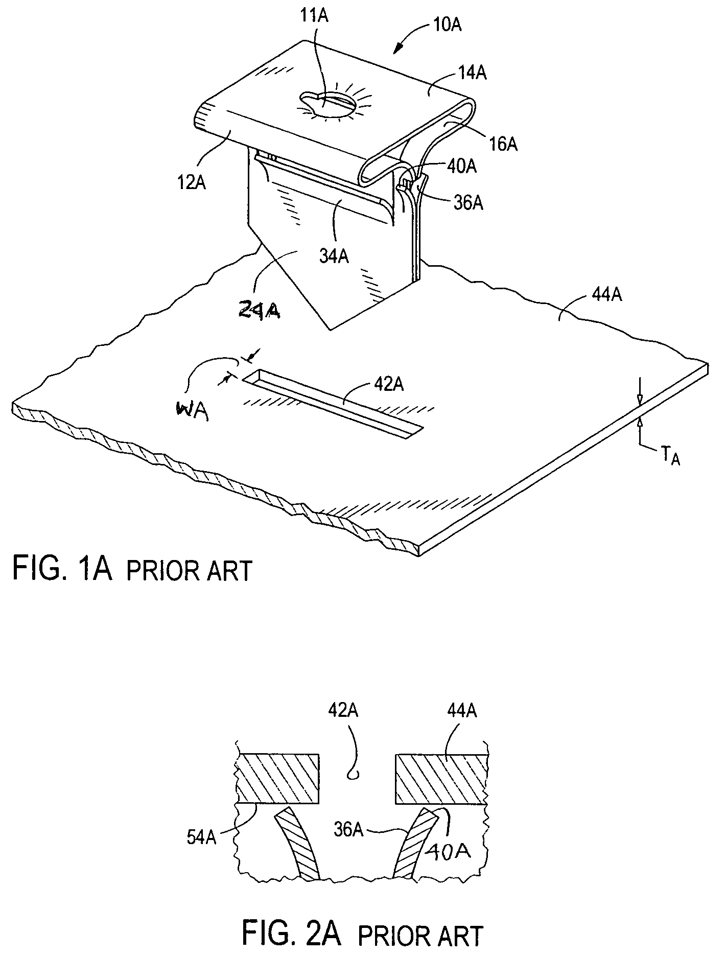
[0037]FIGS. 1A and 2A illustrate fasteners of the present state in the art. The spring fastener 10A comprises a head 12A, which ha...


PUM


Abstract

The present invention pertains fasteners with critical configuration of the barbs, which allows the fasteners to be used in slots of various widths and panels of various thicknesses, and prevents rattling, which would take place in the case of fasteners of the present state of the art. The critical configuration is based on the special dimensions and special shape of the barbs with regard to the parts and the slots involved in assemblies of the fasteners and the parts. The present invention also pertains assemblies of miscellaneous parts connected together by means of the fasteners, as well as vehicles comprising such assemblies. In addition, the present invention comprises fasteners providing a combination of low barbs and high bent barbs, which combination prevents rattling of the fastener and allows secure attachment on a part, such as a sheet metal, for example.

Description

RELATED APPLICATIONS[0001]This application is a Continuation In Part of U.S. Pat. No. 6,835,037 Ser. No. 10 / 729,311, filed Dec. 5, 2003, which is a Divisional Application of U.S. Pat. No. 6,848,874 Ser. No. 10 / 209,765, filed Aug. 1, 2002, both of which are incorporated herein by reference.FIELD OF THE INVENTION[0002]This invention pertains fasteners, and more particularly fasteners which have expandable legs and which attach one object to another object. It also pertains combinations of one or more objects with said fastener(s), assemblies of fasteners with a part, parts or objects connected with the fastener(s), as well as vehicles comprising parts connected with said fastener(s).BACKGROUND OF THE INVENTION[0003]In the original conventional technology of fasteners employed to securely attach one object to another, such as for example one part to another in the case of an automobile or an appliance, has utilized a nut on one of the two objects, usually welded or glued to the back of...

Claims


Application Information

Patent Timeline
Patent Type & Authority Patents(United States)
IPC IPC(8): F16B13/06F16B37/02F16B37/04
CPCF16B37/02F16B37/043Y10T24/189
Inventor LOWRY, JOSEPH WILLIAMVASSILIOU, EUSTATHIOS
Owner EUSTATHIOS VASSILIOU ROVOCABLE TRUST U A D 12 25100
Why Eureka
Try Eureka