Optical device and manufacturing method thereof
a manufacturing method and optical fiber technology, applied in the field of optical fiber devices, can solve the problems of increasing transmission capacity, limiting the dimensional accuracy of components, and the positioning accuracy of components, so as to reduce the size of optical waveguide devices, and simplify the effect of the optical axis adjustment work
- Summary
- Abstract
- Description
- Claims
- Application Information
AI Technical Summary
Benefits of technology
Problems solved by technology
Method used
Image
Examples
first embodiment
[A] Description of the First Embodiment
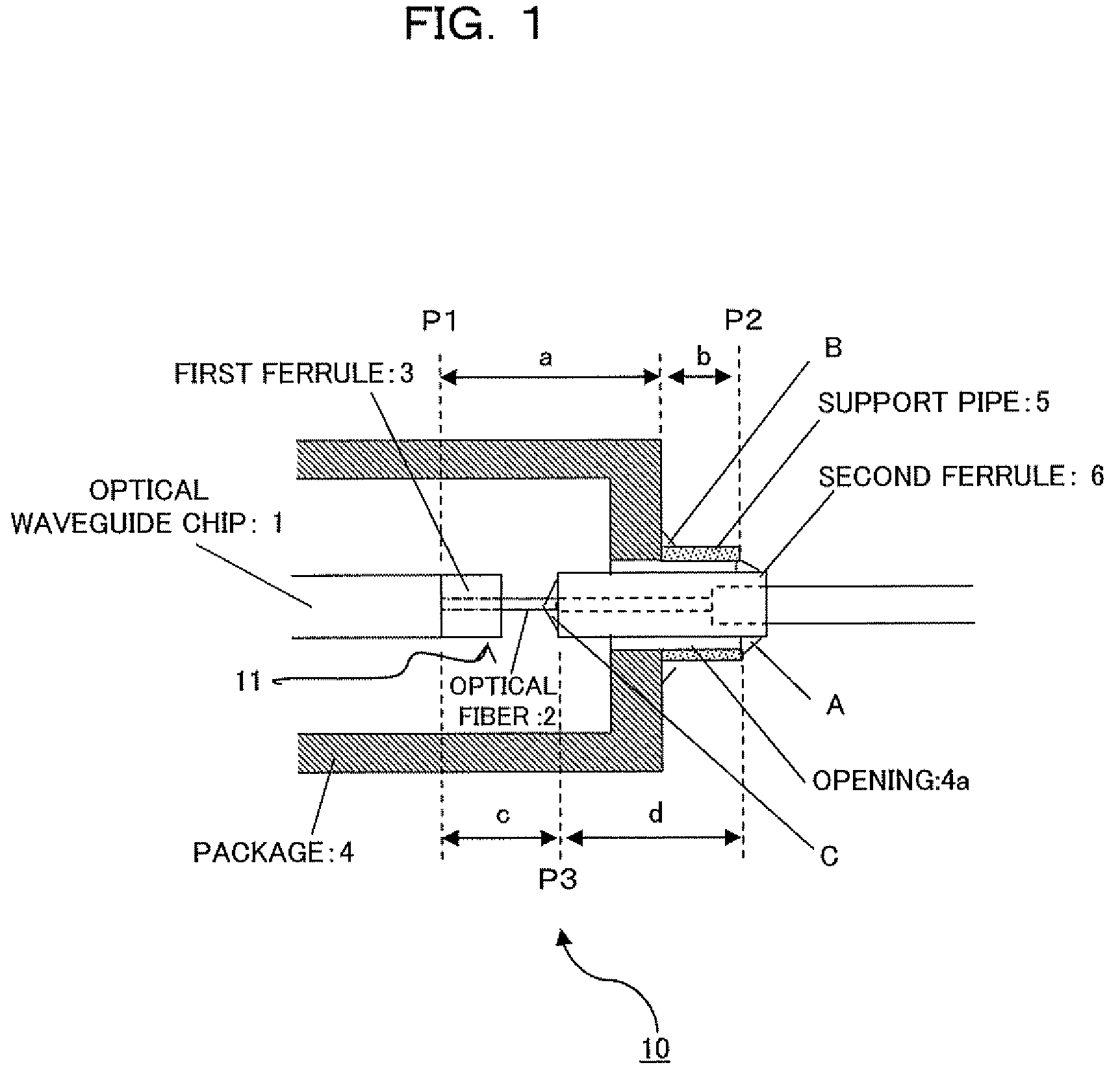
[0059]FIG. 1 is a schematic top view showing an optical waveguide device 10 according to the first embodiment of the present invention and shows the optical waveguide device 10 by focusing particularly on conduction connection of an optical waveguide chip 1 constituting the optical waveguide device 10 and an optical fiber 2 leading to the outside of a package 4. The optical waveguide device 10 shown in FIG. 1 comprises the optical waveguide chip 1, the optical fiber 2, a first ferrule 3, the package 4, a support pipe (first pipe) 5, and a second ferrule 6.
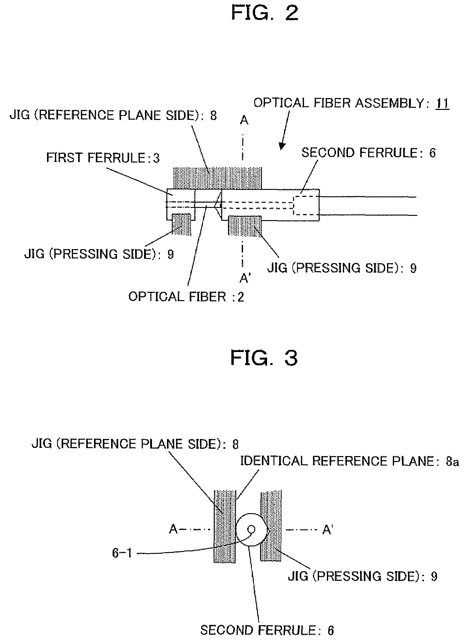
[0060]Here, the optical waveguide chip 1 is, for example, an LN substrate chip on which an optical waveguide is formed as an optical element and can be applied, for example, as a light modulation element chip (optical element chip) (See numeral 102 in FIG. 13) that performs light modulation of input light. The optical fiber 2 is optically connected to the optical waveguide constituting the opt...
second embodiment
[B] Description of the Second Embodiment
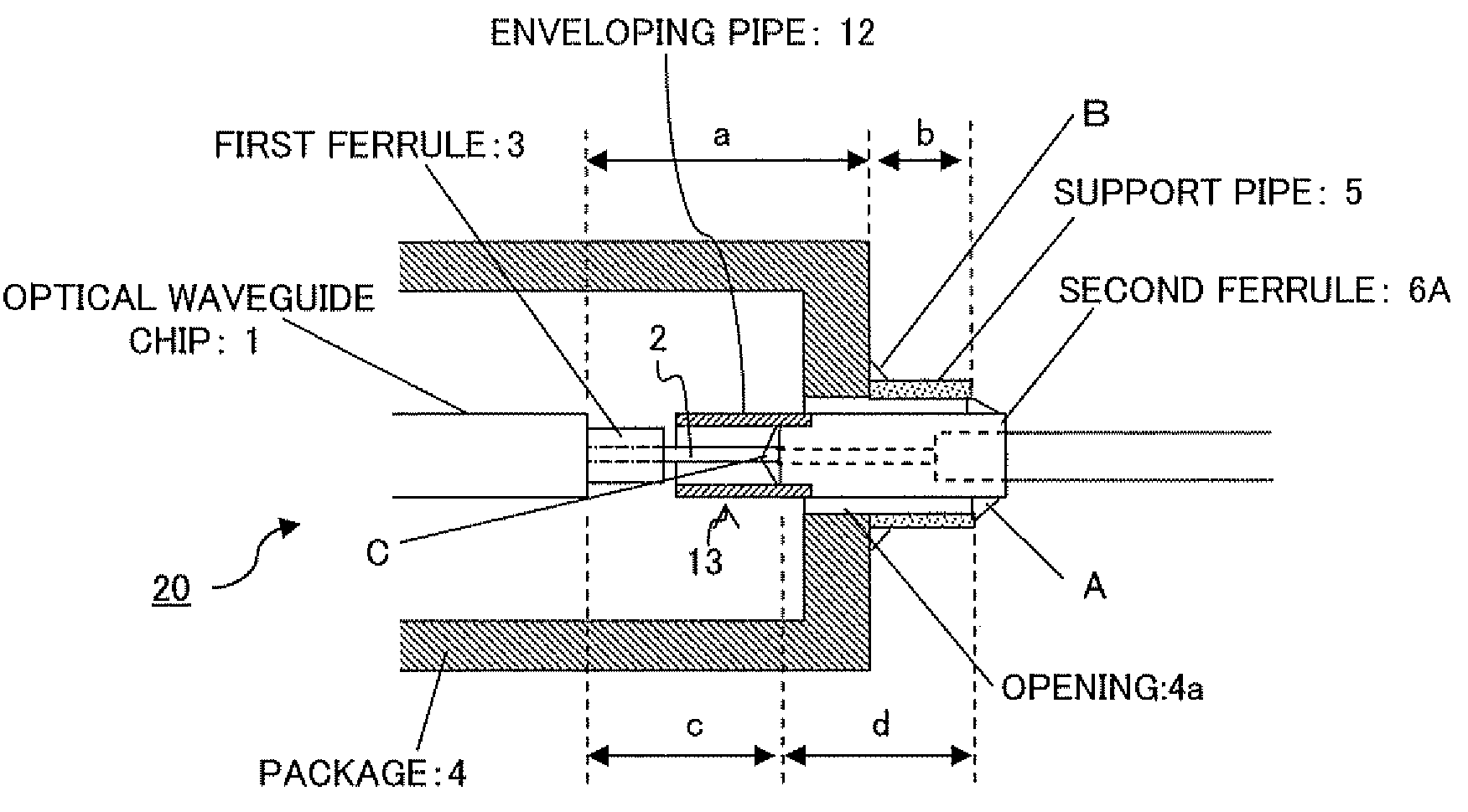
[0105]FIG. 4 is a schematic top view showing an optical waveguide device 20 according to the second embodiment of the present invention and shows the optical waveguide device 20 by focusing particularly on conduction connection of the optical waveguide chip 1 constituting the optical waveguide device 20 and the optical fiber 2 leading to the outside of the package 4. In contrast to the optical waveguide device 10 in the first embodiment described above, the optical waveguide device 20 shown in FIG. 4 has an enveloping pipe (second pipe) 12 mounted on the tip part of the second ferrule 6A on an inner side of the package 4. While the enveloping pipe 12 is mounted on a second ferrule 6A, other configuration is basically the same as that of the above-described first embodiment. The same numerals in FIG. 4 as those in FIG. 1 denote approximately the same components.
[0106]Here, the second ferrule 6A has the external diameter smaller than the interna...
third embodiment
[C] Description of the Third Embodiment
[0139]FIG. 7 is a schematic top view showing an optical waveguide device 30 according to the third embodiment of the present invention. The optical waveguide device 30 shown in FIG. 7 is different from the optical waveguide device 10 in the first embodiment described above in that 2-core optical fibers 2-1 and 2-2 are used for conduction. Accordingly, two fiber insertion holes are provided in first and second ferrules 35 and 6B respectively (See numerals 6-1 and 6-2 shown in FIG. 9 with respect to the second ferrule 6B). The same numerals in FIG. 7 as those in FIG. 1 denote approximately the same components.
[0140]When assembling the optical waveguide device 30 in the third embodiment, like the first embodiment (See numeral 11), an optical fiber assembly 31 shown in FIG. 8 is constructed from the first ferrule 3B, second ferrule 6B, and optical fibers 2-1 and 2-2. FIG. 9 shows an AA′ cross section shown in FIG. 8. As shown in FIG. 8 and FIG. 9, ...
PUM
 Abstract
Description
Claims
Application Information
 - R&D
- Intellectual Property
- Life Sciences
- Materials
- Tech Scout
- Unparalleled Data Quality
- Higher Quality Content
- 60% Fewer Hallucinations
Browse by: Latest US Patents, China's latest patents, Technical Efficacy Thesaurus, Application Domain, Technology Topic, Popular Technical Reports.
© 2025 PatSnap. All rights reserved.Legal|Privacy policy|Modern Slavery Act Transparency Statement|Sitemap|About US| Contact US: help@patsnap.com


